Screw mechanism

a screw mechanism and screw technology, applied in the direction of screws, fastening means, washers, etc., can solve the problems of increasing weight, low reliability of the tightening state, and inability to ensure that the tightening axial force actually applied to the bolt conforms to the designed value, etc., to achieve easy and surely, strong tightening force, easy and surely

Inactive Publication Date: 2005-11-22
YAMAZAKI MASAKI
View PDF29 Cites 61 Cited by
  • Summary
  • Abstract
  • Description
  • Claims
  • Application Information

AI Technical Summary

Benefits of technology

[0041]When the friction force between the screw member on the tightening side and the first washer is configured to be two to four times the friction force between the inclined surfaces of both of the washers, and also as small as possible within the range of being surely bigger than the friction force between the inclined surfaces of both of the washers, it makes it difficult to countervail the tightening-rotating-force of the screw member on the tightening side by the friction force between the screw member on the tightening side and the first washer, thereby an even stronger tightening force is maintained.
[0042]When a non-slip-protrusion-group is provided on the seating-surfaces that contact with each of the opposing surfaces of the screw member on the tightening side and the member to be tightened, and the hardness of the opposing surface of the screw member on the tightening side is made to be lower than the hardness of the non-slip-protrusion-group, and the hardness of the opposing surface of the member to be tightened is made to be lower than the hardness of the opposing surface of the screw member on the tightening side, the above-mentioned action and effect is achieved easily and surely, due to following reason. Since the friction force increases by making the non-slip-protrusion-group dig in to the opposing surface of the member to be tightened even harder, even when using the same washers having a non-slip-protrusion-group installed on the seating-surface as the first and second washers, the friction force between the screw member on the tightening side and the first washer can be made smaller than the friction force between the member to be tightened and the second washer.
[0043]When a non-slip-protrusion-group is provided on the seating-surfaces that contact with each of the opposing surfaces of the screw member on the tightening side and the member to be tightened, and a non-slip-protrusion-group of a different pitch is provided on the opposing surface of the screw member on the tightening side, the above-mentioned action and effect is achieved easily and surely, due to following reason. The friction force between the screw member on the tightening side and the first washer can be made smaller, because the friction force decreases with the non-slip-protrusion-group of a different pitch coming in contact.
[0044]When the non-slip-protrusion-group is constituted by plural streaks of non-slip-protrusion-bands in the annular or radius direction, and arranged and installed with an appropriate interval, the forming of the non-slip-protrusion-group by a knurling process is made easy, and the control of the friction force is also done easily.
[0045]When a friction-force-adjusting-sheet is interposed between the opposing surface of the screw member on the tightening side and the seating-surface of the first washer, the following is possible. It is possible to achieve a state in which, the friction force between the opposing face of the screw member on the tightening side and the seating-surface of the first washer is as small as possible within the range of being bigger than the friction force between the inclined surfaces, easily with precision. When the friction-force-adjusting-sheet is composed of a cloth or a paper containing abrasive-grains, it is possible to achieve a friction force surely, compared to a case in which a thin metal sheet is used, for example, and the friction force is adjusted with precision. And the cost will be low, and the handling easy.
[0046]A latching-ring has a planar and C-lettered form, and is capable of being elastically fit onto the outer circumference of the first and second washers, and has a tongue piece installed in protrusion on the inner circumference thereof. This tongue piece fits into a clearance generated between the tier faces of the first and second washers, in a state of reverse-lock, which locks by rotating in the opposite direction of the tightening direction after tightening the screw member on the tightening side. When this latching-ring is installed, and fit onto the outer circumference of the first and second washers, the state of reverse-lock is surely maintained by the tongue piece. This prevents the occurrence of a situation in which the screw member on the tightening side and the first washer rotate along the inclination of the inclined surface due to vibration, the reverse-lock is canceled unexpectedly, and the non-loosening-effect is decreased.

Problems solved by technology

However, there was no guarantee that the tightening axial force actually applied to a bolt conformed to the designed value, even when the tightening rotational torque was kept constant, due to the friction coefficient between a head portion of a bolt or a nut and a washer, the friction coefficient between the washer and a member to be tightened, the dispersion of the friction coefficient on the screw surface, and deposits such as dust or oil on each of the contacting surfaces.
Thereby the reliability of the tightening state was low.
It was also necessary to tighten with multitudes of bolts and nuts for maintaining safety, causing an increase in weight, and a vicious circle was generated requiring an increase in bolts and nuts to correspond to the weight increase, and there was a problem of the cost increase.
However, the spring washer does not necessarily perform a sufficient loosening-preventing-effect, and the locknut cannot always be used, because it is necessary to protrude the male screw member from the female screw member for a large amount, in order to use the locknut.
However, it is especially difficult to process the bordering portions between the cam faces 56, 59, and the tier faces 57, 60, in high precision, and the above-mentioned effects cannot be achieved when there is unevenness or protrusions in this border portion.
Hence, there was a problem that the cost became high due to the high precision processing, and not practical.
So there was a problem that not enough tightening force was achieved for the mounting member 53, in comparison to the applied rotation torque, and a shortage of the tightening force occurred.
And there was a problem that it was difficult to fulfill both of these requirements.
An expensive material or a heat-treatment is required to prevent such an occurrence, and there was a problem that the cost increases.
In case of tightening and fixing a mounting member with low anti-crack characteristics, such as glass or ceramics, it was not possible to tighten firmly because there was fear of generating a crack due to the tightening.
And there was a problem that it was very difficult to achieve a loosening-prevention effect.

Method used


Image

  • Screw mechanism
  • Screw mechanism
  • Screw mechanism

Examples


first embodiment

[0070]a screw mechanism and a tightening method of the present invention will be described in the following, with reference to FIG. 1 to FIG. 5.

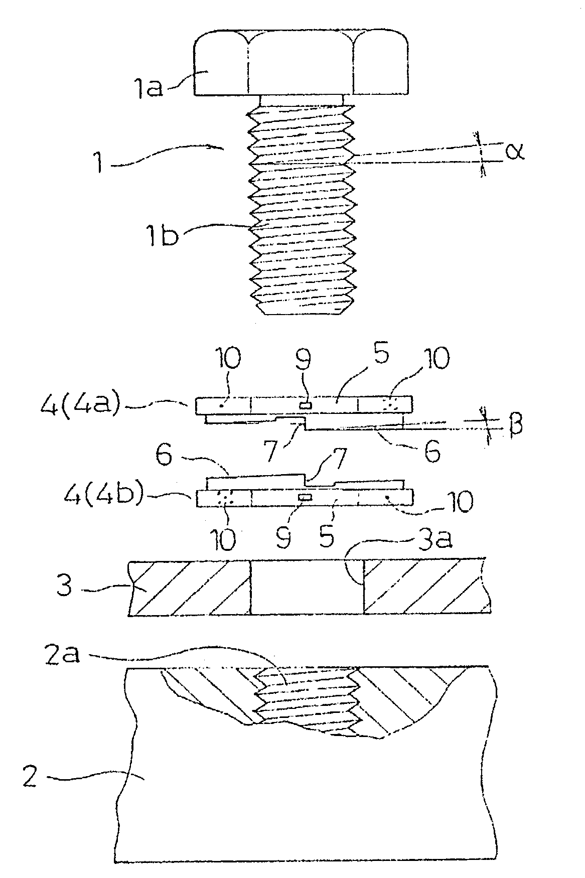
[0071]In FIG. 1 to FIG. 4, reference numeral 1 denotes a male screw member consisting of a bolt, reference numeral 2 denotes a female screw member consisting of a construction member that has a female screw 2a formed thereinside. In this embodiment indicated is a case in which a member 3 to be tightened is arranged on top of this construction member 2, and tightened and fixed to the female screw member (construction member) 2, by making the male screw member 1 penetrate through a bolt hole 3a formed on the member 3 to be tightened.

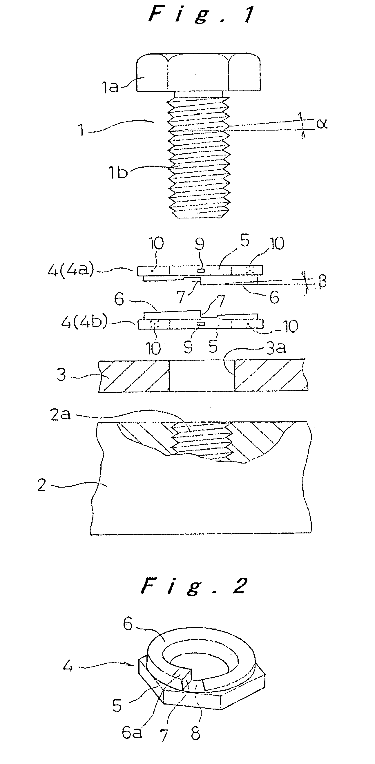
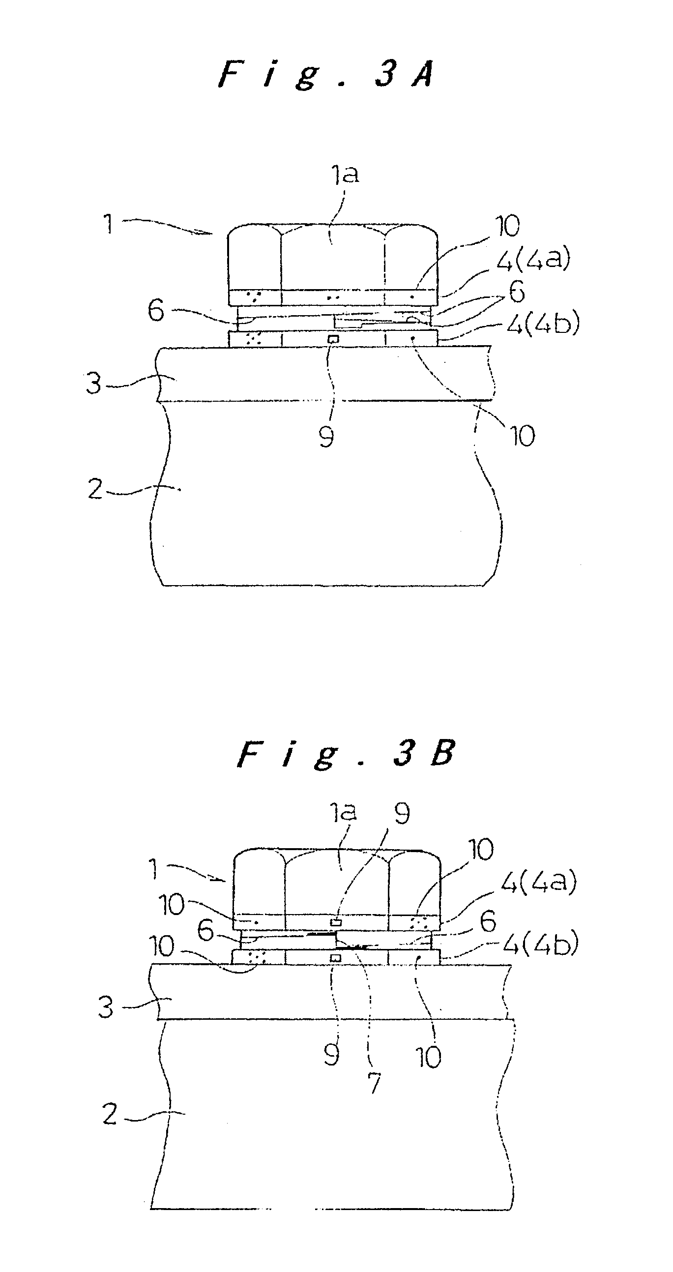
[0072]The male screw member 1 has a hexagonal head portion 1a and a male screw 1b, and a pair of washers 4 (4a, 4b) of the same construction are interposed between this head portion 1a and the member 3 to be tightened in a mutually upside-down direction, in a state of being fitted to the outer circumference of the ...

second embodiment

[0083]the present invention is described in the following, with reference to FIG. 6. In the above-mentioned embodiment, an example was indicated that used the male screw member 1 having the head portion 1a, and the female screw 2a was formed on the construction member to form the female screw member 2. However in this embodiment, it is constituted so that a male screw member 11 is embedded and fixed to a construction member 2, and a member 3 to be tightened is arranged on top of the construction member 2, by making the male screw member 11 inserted through a bolt hole 3a formed on the member 3 to be tightened to tightened this member 3 to be tightened with a nut member 12 acting as a female screw member. In this case, the same action and effect with the above-mentioned embodiment is also performed, by making a pair of washers 4 (4a, 4b) be interposed between the nut member 12 and the member 3 to be tightened.

[0084]In this embodiment, an example of a case in which the male screw memb...

fourth embodiment

[0086]the present invention is described in the following, with reference to FIG. 8. In the above-mentioned embodiment, an example was shown with the washer 4 being formed to a deformed-member-form the same form as the head portion 1a of the male screw member 1. In other words, the seat portion 5 was formed in a polygon form. In this embodiment, the washer 14 is provided with a seat portion 15 of disc form with non-slip-means such as knurls formed on the circumference, and made so that the interval between the tier faces 7, 7 can be made a random angle, without being restricted by the polygon shape. A graduation 16 is also formed on the outer circumference along one direction of the inclined direction, starting from the formed position of the tier face 7. This enables an easy perception of the interval size when configuring the interval between the tier faces 7, 7, and makes it possible to configure the desired tightening force.

[0087]It is preferred that this pair of washers 14 (14a...


PUM


Abstract

In a screw locking assembly a pair of washers having inclined surfaces are interposed between a screw member on a tightening side and a member to be tightened, with the inclined surfaces being mutually contacted. These inclined surfaces circle around once in spiral form with a lead angle β smaller than a lead angle α of the screw, and both ends thereof are connected with a tier face in the axial direction. By conducting an initial-tightening in a state with an interval of a preset angle maintained between the tier faces, and tightening and rotating the screw member on the tightening side until the tier faces come into contact with each other, a tightening force proportional to that angle is generated, and the tightening force is controlled surely with precision.

Description

TECHNICAL FIELD[0001]The present invention relates to a screw mechanism that tightens and fixes a member to be tightened by making a male screw member and a female screw member screwed together, and particularly to a screw mechanism that surely control the tightening force with precision, and also surely prevent a screw from loosening by vibration, and achieve a highly reliable tightening condition.BACKGROUND ART[0002]Conventionally, when a member to be tightened is tightened and fixed by screwing a bolt or a nut to a female screw, a nut, or a bolt, the following method was generally adopted to prevent an occurrence of loosening due to insufficient tightening force (tightening axial force), or to prevent damage to a member due to excessive tightening force. That is, the tightening rotational torque was controlled to a prescribed value by tightening a bolt or nut with a torque wrench, in order to maintain an appropriate tightening state with a prescribed tightening force.[0003]Howeve...

Claims


Application Information

Patent Timeline
Patent Type & Authority Patents(United States)
IPC IPC(8): F16B39/24F16B43/00F16B39/00
CPCF16B39/24F16B43/009
Inventor YAMAZAKI, MASAKI
Owner YAMAZAKI MASAKI
Why Eureka
Try Eureka