
Method and apparatus for using barrier phases to limit packet disorder in a packet switching system

a packet switching and barrier phase technology, applied in data switching networks, frequency-division multiplexes, instruments, etc., can solve problems such as complex techniques, large buffers and sequence number counters, and large resources for buffers and sequence numbers

Inactive Publication Date: 2005-11-22
CISCO TECH INC
View PDF30 Cites 69 Cited by
  • Summary
  • Abstract
  • Description
  • Claims
  • Application Information

AI Technical Summary

Benefits of technology

The patent describes a way to prevent confusion in a network system by using barrier phases to organize packets. This helps to ensure that packets are sent in the correct order and reduces errors.

Problems solved by technology

This technique is simple, but it requires significant resources for the buffers and sequence number counters.
This problem is further compounded when contiguous sequence numbers are not used or when a packet is lost or dropped.
In either of these cases, it is hard to determine whether certain packets should be forwarded immediately or should be delayed to see if the potentially dropped or lost packet or a packet with the skipped sequence number actually arrives.

Method used


Image

  • Method and apparatus for using barrier phases to limit packet disorder in a packet switching system
  • Method and apparatus for using barrier phases to limit packet disorder in a packet switching system
  • Method and apparatus for using barrier phases to limit packet disorder in a packet switching system

Examples


Embodiment Construction

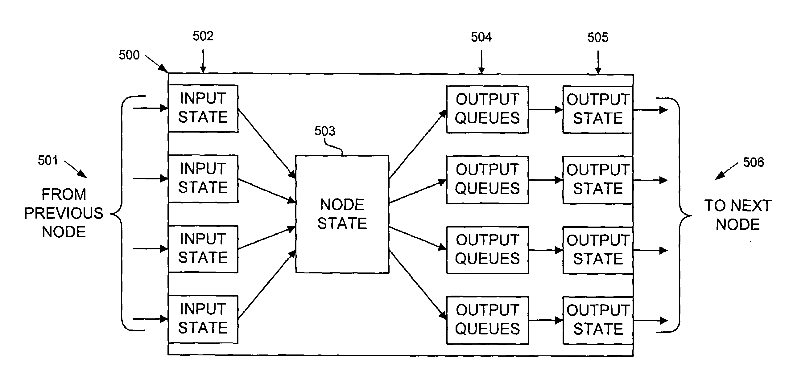
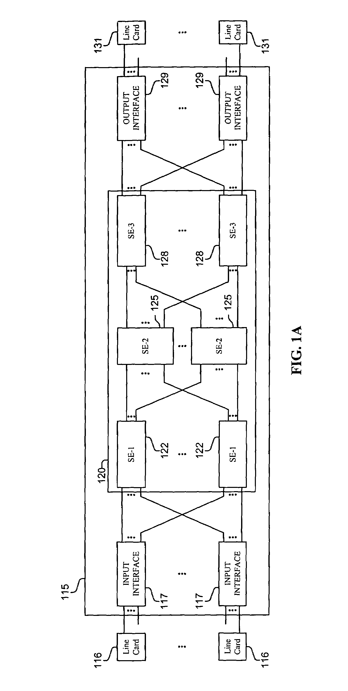
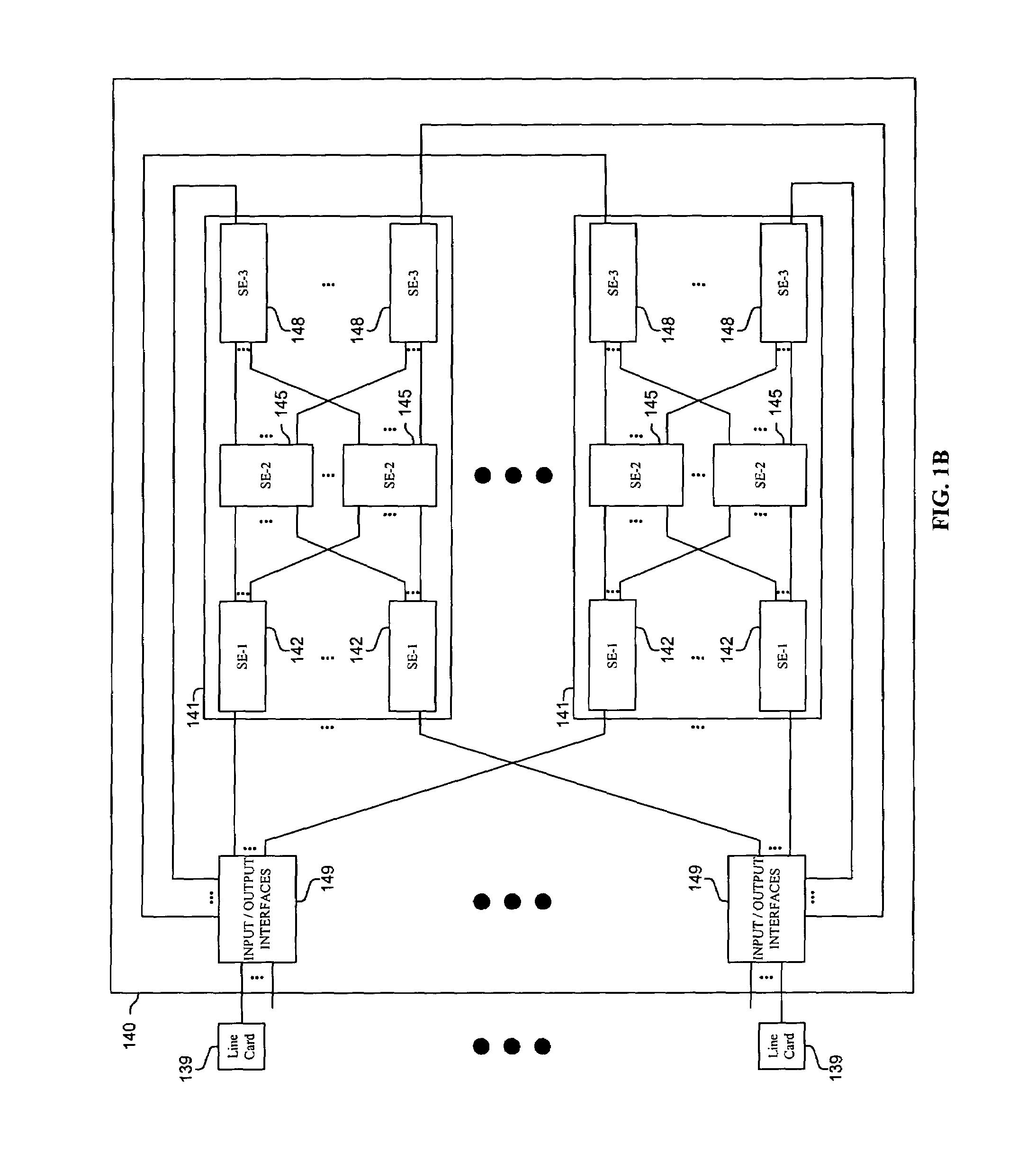
[0018]Methods and apparatus are disclosed for using barrier phases to limit the disorder of packets which may be used, inter alia, in a computer or communications system, such as a packet switching system, router, or other device. Such methods and apparatus are not limited to a single computer or communications system. Rather, the architecture and functionality taught herein are extensible to an unlimited number of computer and communications systems, devices and embodiments in keeping with the scope and spirit of the invention. Embodiments described herein include various elements and limitations, with no one element or limitation contemplated as being a critical element or limitation. Each of the claims individually recite an aspect of the invention in its entirety. Moreover, some embodiments described may include, but are not limited to, inter alia, systems, integrated circuit chips, embedded processors, ASICs, methods, and computer-readable medium containing instructions. The em...


PUM


Abstract

Methods and apparatus are disclosed for using barrier phases to limit the disorder of packets which may be used in a computer or communications system. In one packet switching system, source nodes include an indication of their current barrier state in sent packets. For each barrier state, a predetermined range of sequence numbers may be used or a predetermined number of packets may be sent by a source node. The source, destination, and switching nodes are systematically switched between barrier phases, which is typically performed continuously in response to the flow of barrier request and barrier acknowledgement packets or signals. Each source node broadcasts to all forward connected nodes a barrier request to change to a next barrier state. After a switching node has received a barrier request on all incoming links, the switching node propagates the barrier request. Upon receiving barrier requests over all links, each destination stage relays an acknowledgement message to all connected source elements, which then send a barrier acknowledgement in much the same way, and each source element changes its barrier state causing the sequence number or counting space to be reset, and newly sent packets to indicate the new barrier state. Upon receiving all its barrier acknowledgement messages, each destination stage changes its barrier state, and then the destination can manipulate (e.g., resequence, reassemble, send, place in an output queue, etc.) packets marked with the previous barrier state as it knows that every packet from the previous barrier state has been received. This transition of barrier phases and limiting the number of packets sent per barrier phases may be used to limit the range of the sequence number space and the size of outgoing, resequencing, and reassembling buffers, as well providing a packet time-out mechanism which may be especially useful when non-continuous sequence numbers or time-stamps are included in packets for resequencing and / or reassembly purposes.

Description

FIELD OF THE INVENTION[0001]This invention relates to a packet switching system of communications systems, routers, computers and communications devices; and more particularly, the invention relates to using barrier phases to limit packet disorder in a packet switching system.BACKGROUND OF THE INVENTION[0002]The communications industry is rapidly changing to adjust to emerging technologies and ever increasing customer demand. This customer demand for new applications and increased performance of existing applications is driving communications network and system providers to employ networks and systems having greater speed and capacity (e.g., greater bandwidth). In trying to achieve these goals, a common approach taken by many communications providers is to use packet switching technology.[0003]As used herein, the term “packet” refers to packets of all types, including, but not limited to, fixed length cells and variable length packets, each of which may or may not be divisible into ...

Claims


Application Information

Patent Timeline
Patent Type & Authority Patents(United States)
IPC IPC(8): H04L12/56H04L12/00
CPCH04L47/10H04L47/24H04L47/26H04L47/33H04L47/34H04L49/1523H04L49/90H04L49/9094
Inventor WILLIAMS, JR., JOHN J.DEJANOVIC, THOMASMICHELSON, JONATHAN E.
Owner CISCO TECH INC
Learn More