
Method of drying metallic waste of pyrophoric tendencies that is to be compacted; apparatus and compacting canister associated with said method

a technology of pyrophoric tendencies and compacting canisters, which is applied in the direction of lighting and heating apparatus, combustion types, furnaces, etc., can solve the problems of poor radiation heating performance of resistance elements placed around the canister, conventional drying techniques, and poor adaptation to the nature of contaminated waste in question, so as to reduce the entrainment of dust

Inactive Publication Date: 2005-11-29
COGEMA SA
View PDF15 Cites 0 Cited by
  • Summary
  • Abstract
  • Description
  • Claims
  • Application Information

AI Technical Summary

Benefits of technology

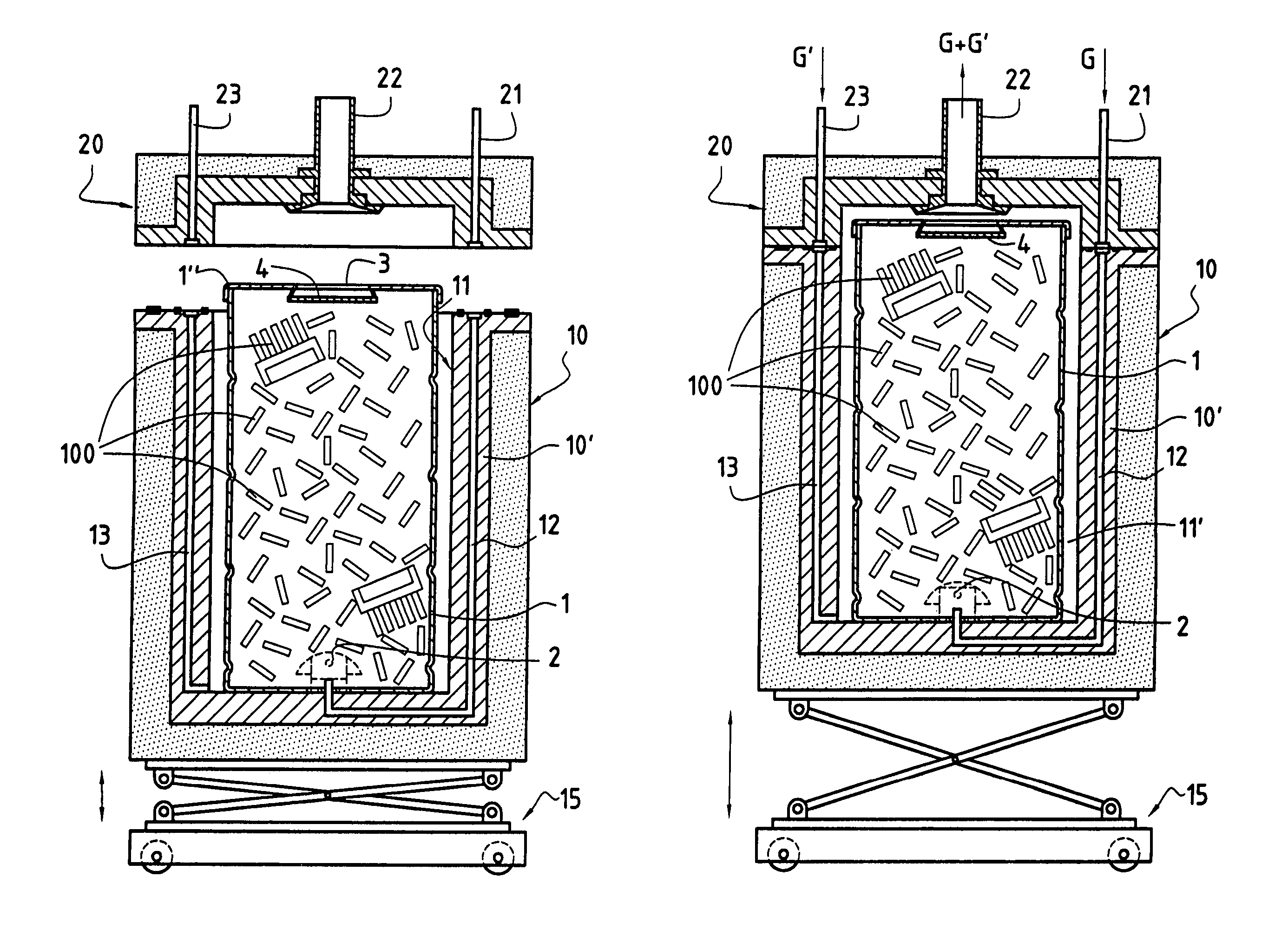
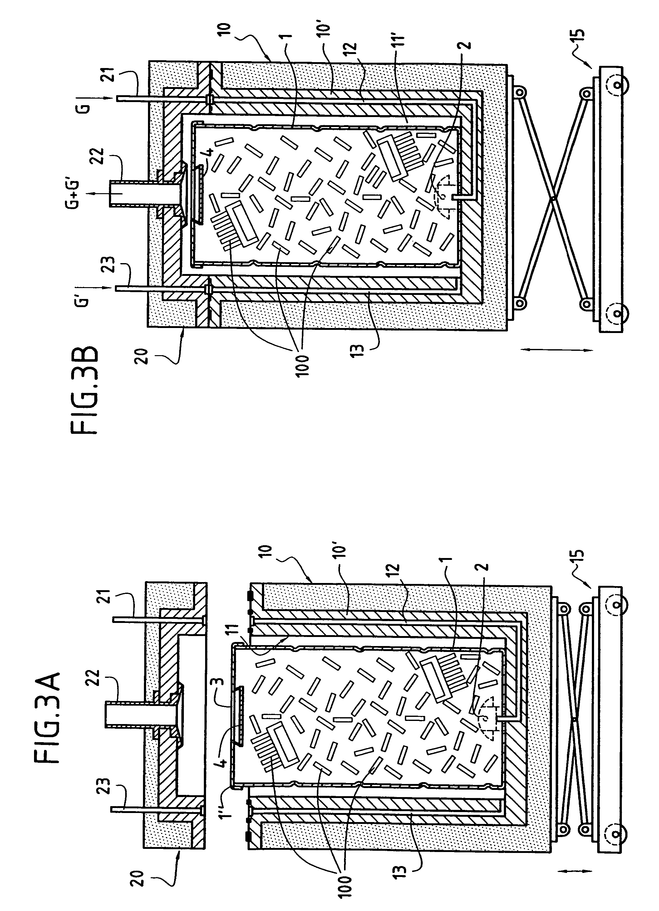
[0041]The involvement of this sweeping inert gas (G′) (identical or different, advantageously identical in nature with the drying inert gas (G)) is advantageous for establishing counter-pressure and thus avoiding any leakage of the drying inert gas (G) (possibly carrying dust) into the fraction of the hermetically closed volume that is then not occupied by the canister, i.e. in the cavities of the docked moving enclosure. Said sweeping inert gas (G′) is advantageously used hot, so that heat losses from the canister to the enclosure are limited.
[0050]Whatever the implementation of the method of the invention, and most particularly in the context of the above preferred implementation, it is advantageous to limit loss of heat conveyed by the drying inert gas (G). For this purpose, the moving enclosure in which the waste-loaded canister is positioned is itself thermally insulated (advantageously covered in suitable lagging) and / or the sweeping inert gas (G′) used is advantageously delivered hot.
[0076]For introducing the gas, a check valve is advantageously used (said check valve opens under the pressure of the injected gas; it is protected by a bell from any waste that might prevent it from operating properly); for evacuating the gas, at least one evacuation orifice is advantageously provided. The size of said orifice and its association with suitable means can be optimized to minimize the entrainment of dust.

Problems solved by technology

Conventional drying techniques, in an oven or in a stream of gas are poorly adapted to the nature of the contaminated waste in question.
The associated apparatus is open and does not contain means for making it easy to handle such waste which comes in pieces of relatively small size.
Radiation heating by means of resistance elements placed around said canister has been found to be of poor performance (the center of said canister was not heated fast enough) while heating in an oven presented the drawbacks mentioned above, so the Applicant has opted for passing a stream of hot inert gas through said waste packaged in its compacting canister; said canister has been adapted for this purpose.

Method used


Image

  • Method of drying metallic waste of pyrophoric tendencies that is to be compacted; apparatus and compacting canister associated with said method
  • Method of drying metallic waste of pyrophoric tendencies that is to be compacted; apparatus and compacting canister associated with said method
  • Method of drying metallic waste of pyrophoric tendencies that is to be compacted; apparatus and compacting canister associated with said method

Examples


Embodiment Construction

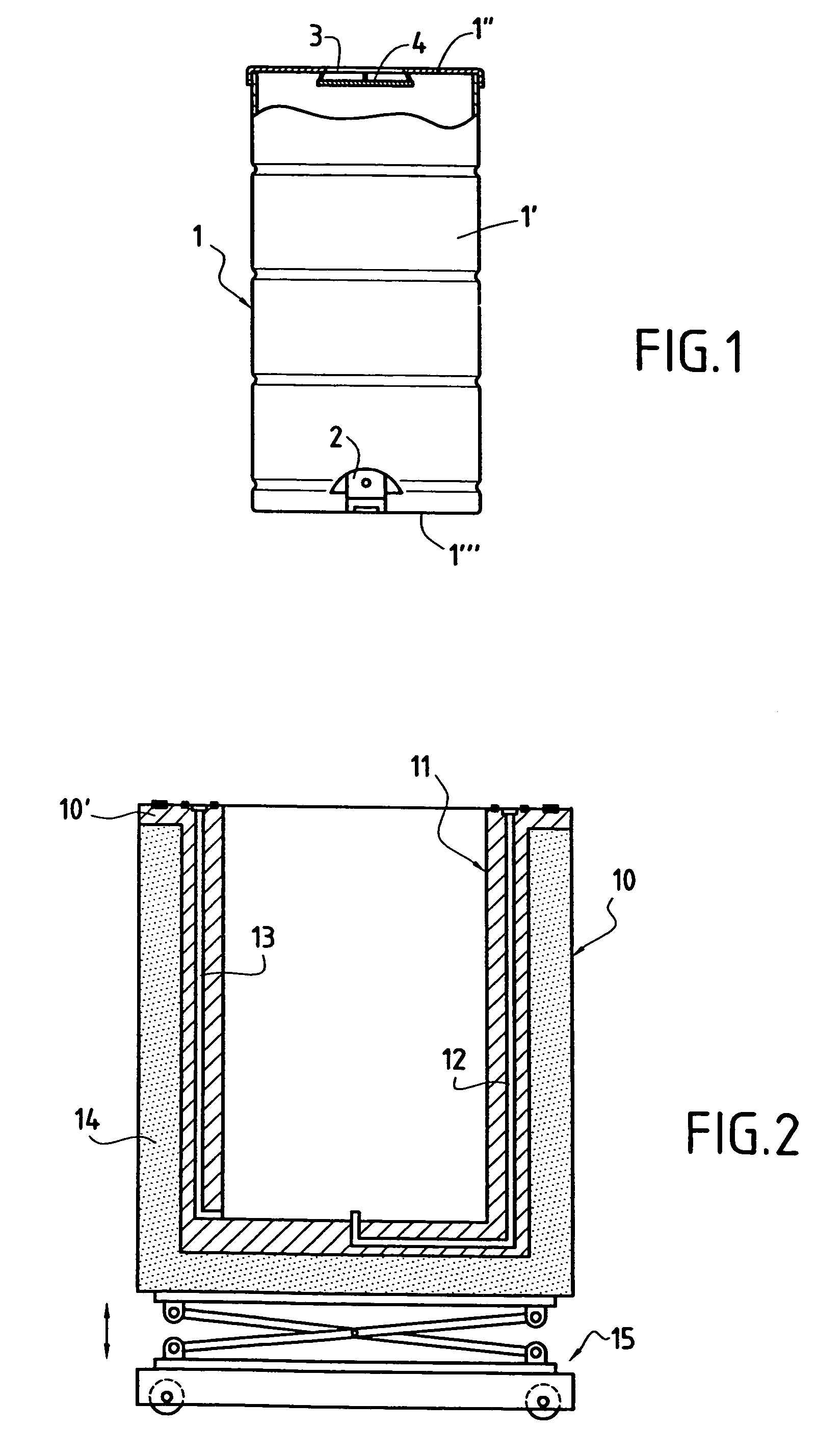
[0097]The compacting canister 1 of FIG. 1 is a conventional canister in that it is cylindrical in shape and presents an axial wall 1′, a cover 1″, and a bottom 1′″. Said cover 1″ closes said canister 1 in non-sealed manner.

[0098]Said compacting canister 1 is a canister of the invention in that it is also fitted with means for introducing gas into its internal volume and for evacuating gas therefrom. The means in question are arranged respectively on its bottom 1′″ and on its cover 1″. For injecting the drying gas, a check valve 2 is provided on said bottom 1′″. For evacuating said gas, an opening 3 is provided on said cover 1″. Upstream from said opening 3 (secured to the inside face of the cover 1″), there is a plate 4. This plate serves to limit to a very great extent the amount of dust that is entrained by the drying gas flowing from the bottom of the canister towards the top. During the subsequent step of compacting the canister, this plate can also serve to shut said canister a...


PUM


Abstract

The present invention provides:a method of drying metallic waste having pyrophoric tendencies (liable to catch fire and / or explode), said waste being for compacting;an apparatus for drying said waste, the apparatus including a compacting canister and being suitable for implementing said drying method; anda canister for compacting said waste, the canister being particularly adapted to implementing said drying method.

Description

CROSS REFERENCE TO RELATED APPLICATIONS[0001]This application is a Divisional of U.S. Pat. application Ser. No. 10 / 613,353, filed Jul. 3, 2003.FIELD OF THE INVENTION[0002]The present invention relates to a method of drying metallic waste having pyrophoric tendencies (liable to catch fire and / or explode), said waste being for compacting.[0003]The invention also provides:[0004]an apparatus for drying such waste, the apparatus including a canister for compacting said waste and being suitable for implementing said drying method; and[0005]a canister for compacting said waste, the canister being particularly adapted to implementing said drying method.[0006]The present invention has been designed and developed in the nuclear context. It is described below more particularly with reference to this context, however the person skilled in the art will readily understand on reading the text below that the principle of the invention—drying material having pyrophoric tendencies in a compacting can...

Claims


Application Information

Patent Timeline
Patent Type & Authority Patents(United States)
IPC IPC(8): F26B3/06G21F9/36F26B9/06F26B21/14F26B25/06G21F9/30
CPCF26B9/06F26B21/14F26B25/063F26B3/06G21F9/36
Inventor LADRE, MAURICELE COCQ, SERGELIMEUIL, GERARD
Owner COGEMA SA
Learn More