Flooring device for positioning on joists

Inactive Publication Date: 2005-11-29
EADIE ROBERT J
View PDF31 Cites 19 Cited by
  • Summary
  • Abstract
  • Description
  • Claims
  • Application Information

AI Technical Summary

Benefits of technology

[0017]It is another object of the present invention to provide a new flooring device for positioning on joists which may be easily and efficiently manufactured and marketed.
[0018]It is a further object of the present invention to provide a new flooring device for positioning on joists which is of a durable and reliable construction.
[0019]An even further object of th

Problems solved by technology

While these devices fulfill their respective, particular objectives and requirements, th

Method used


Image

  • Flooring device for positioning on joists
  • Flooring device for positioning on joists
  • Flooring device for positioning on joists

Examples


Embodiment Construction

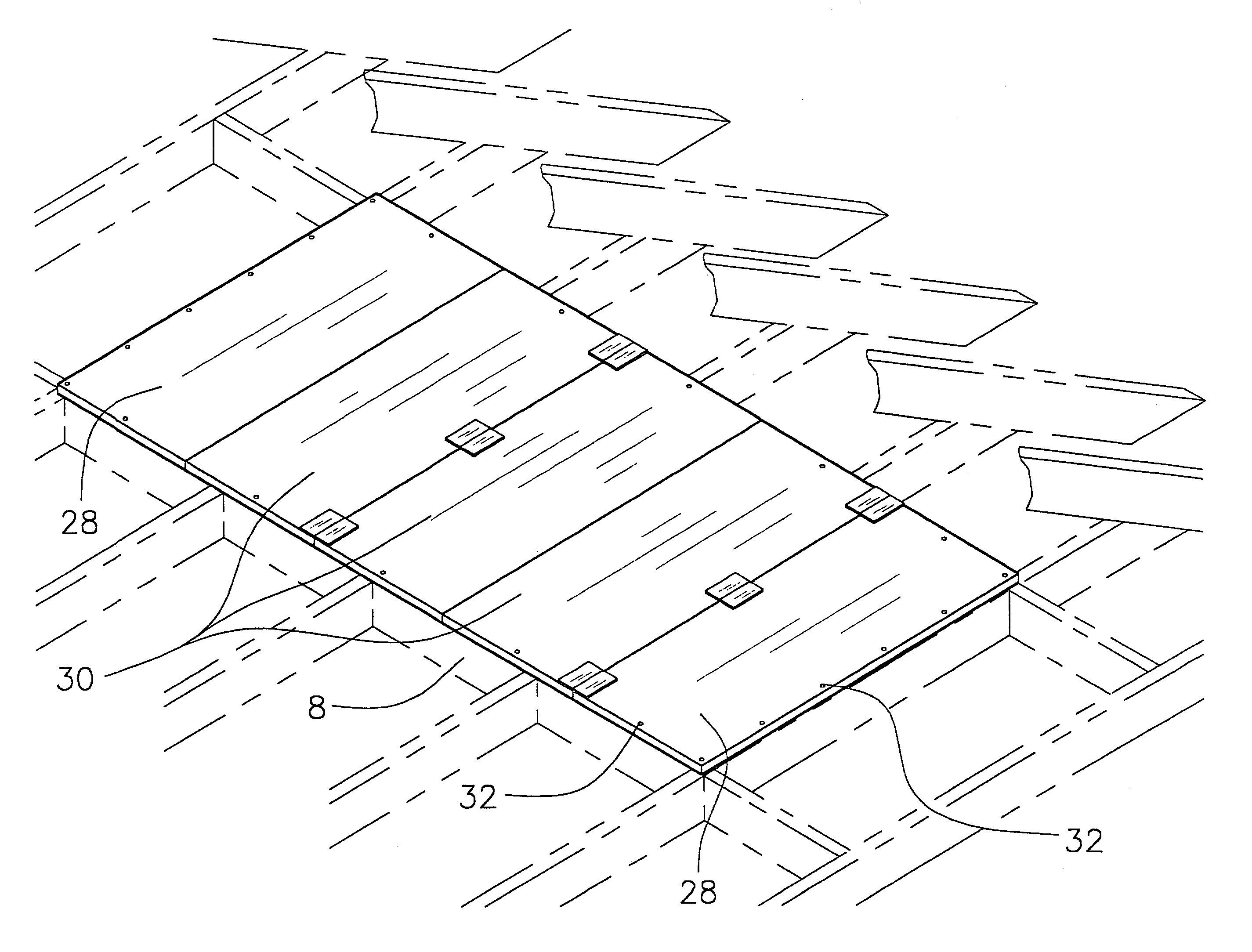
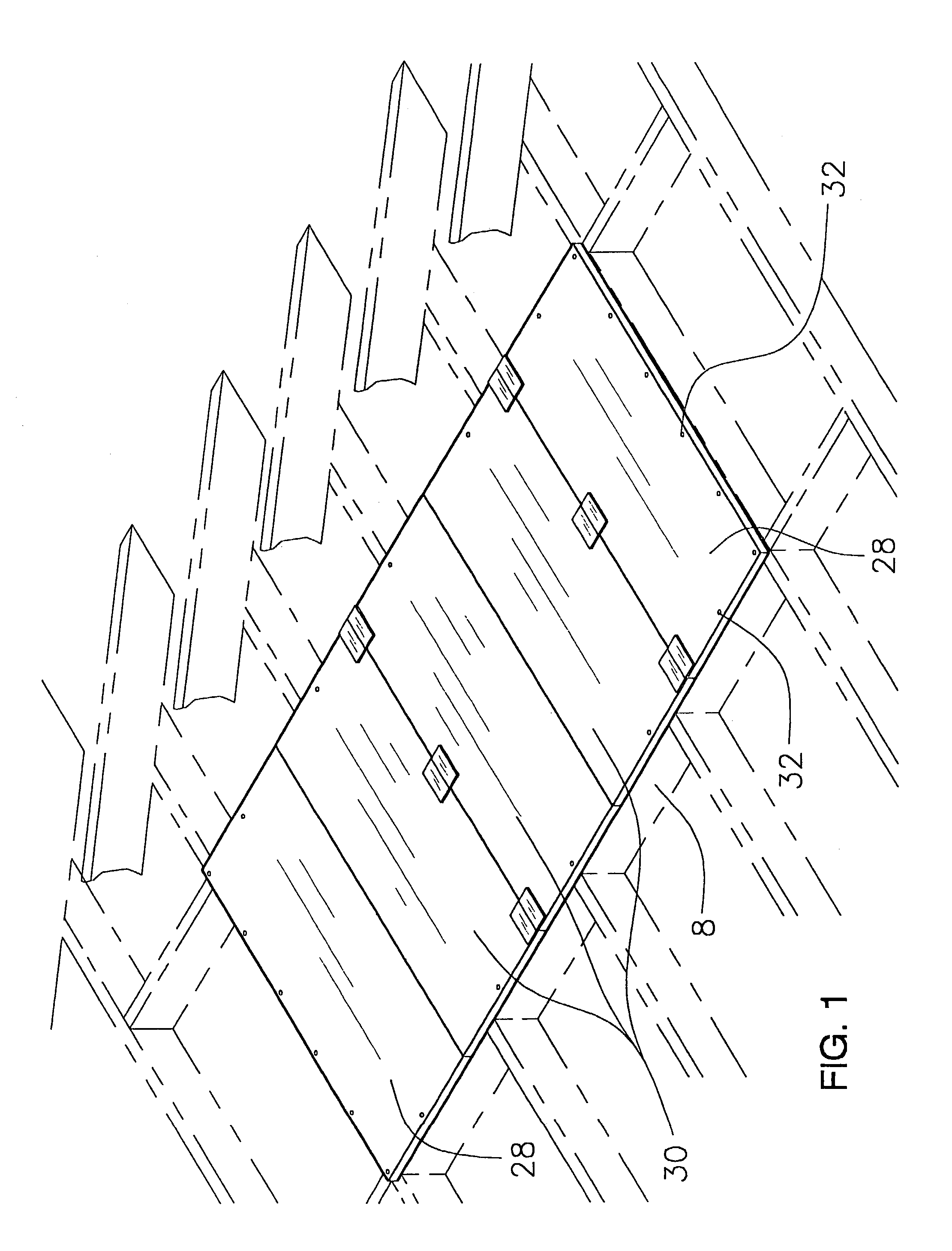
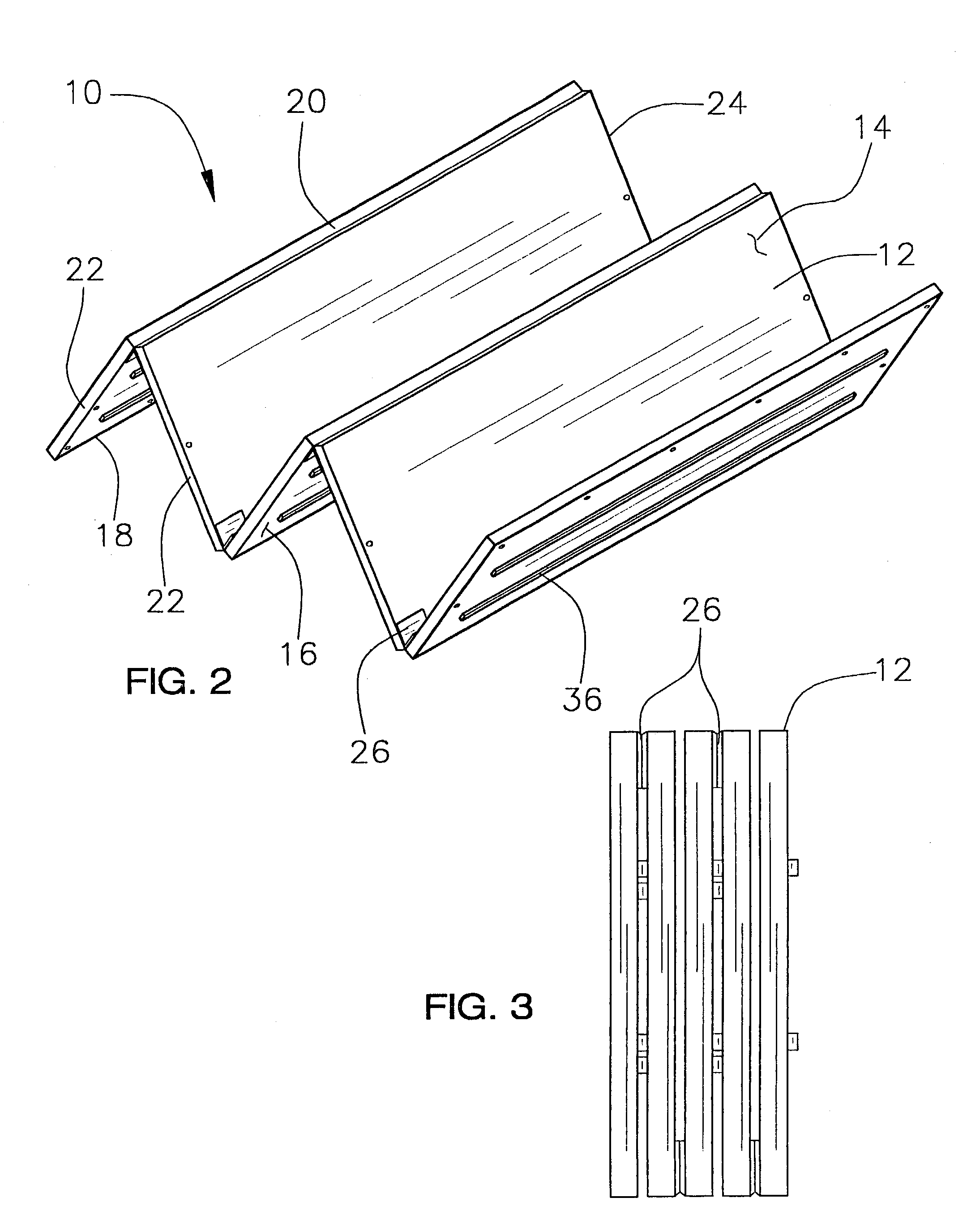
[0032]With reference now to the drawings, and in particular to FIGS. 1 through 5 thereof, a new flooring device for positioning on joists embodying the principles and concepts of the present invention and generally designated by the reference numeral 10 will be described.

[0033]As best illustrated in FIGS. 1 through 5, the flooring device 10 for positioning on joists generally comprises a plurality of rigid panels 12 each having a top side 14, a bottom side 16, a first edge 18, a second edge 20, a third edge 22 and a fourth edge 24. The first 18 and second 20 edges are side edges positioned at opposite locations on the panel, and the third 22 and fourth 24 edges are end edges positioned at opposite locations on the panel. The first 18 and second 20 edges may have a length of approximately 4 feet, and the third 22 and fourth 24 edges may have a length of approximately 2 feet.

[0034]Each of the panels 12 is coupled to at least one other panel by at least one hinge 26. Thus, a first edge...


PUM


Abstract

A flooring device is disclosed for positioning on joists for allowing easy maneuvering on floor joists in an attic. The flooring device includes a plurality of substantially rigid panels arranged adjacent to each other in a series. The invention also includes a connecting mechanism located at a juncture between each of the panels in the series for connecting each panel to an adjacent panel. The connecting mechanism permits adjacent panels of the series to pivot about a pivot axis with respect to each other, with the pivot axis of the mechanism at one juncture of the series being positioned adjacent to the top sides of the panel adjacent to the juncture and the pivot axis of the mechanism at an adjacent juncture being positioned adjacent to the bottom side of the panels adjacent to the juncture such that the series of panels are foldable in accordion fashion between collapsed and extended conditions.

Description

REFERENCE TO RELATED APPLICATION[0001]This application is a continuation-in-part of application Ser. No. 09 / 833,476, filed Apr. 12, 2001 now abandoned.BACKGROUND OF THE INVENTION[0002]1. Field of the Invention[0003]The present invention relates to flooring devices and more particularly pertains to a new flooring device for positioning on joists for allowing easy maneuvering on floor joists in an attic.[0004]2. Description of the Prior Art[0005]The use of flooring devices is known in the prior art. More specifically, flooring devices heretofore devised and utilized are known to consist basically of familiar, expected and obvious structural configurations, not with standing the myriad of designs encompassed by the crowded prior art which have been developed for the fulfillment of countless objectives and requirements.[0006]Known prior art includes U.S. Pat. No. 2,822,585; U.S. Pat. No. 5,033,241; U.S. Pat. No. 1,710,610; U.S. Pat. No. 5,239,790; U.S. Pat. No. 4,599,841; U.S. Pat. No. ...

Claims


Application Information

Patent Timeline
IPC IPC(8): E04B5/12E04C2/38
CPCE04B5/12E04F15/02
Inventor EADIE, ROBERT J.
Owner EADIE ROBERT J
Why Eureka
Try Eureka