Composite joinery

a jointery and composite technology, applied in the field of joint arrangements, can solve the problems of high structure complexity, and achieve the effect of easing the bending of corner panels

Inactive Publication Date: 2005-11-29
NCI GROUP
View PDF27 Cites 110 Cited by
  • Summary
  • Abstract
  • Description
  • Claims
  • Application Information

AI Technical Summary

Benefits of technology

[0011]The present invention also contemplates, in accordance with at least one presently preferred embodiment, a reveal (i.e., an inward recess into at least one of the upper and lower panels) that is considerably deeper than the norm, conceivably two or three times as deep. The advantages include eased bending in corner pan

Problems solved by technology

However, a highly complicated structure is

Method used


Image

  • Composite joinery
  • Composite joinery
  • Composite joinery

Examples


Embodiment Construction

[0046]FIGS. 1–3, and the accompanying disclosure herebelow, are taken from U.S. Pat. No. 5,749,282 (Brow et al.) for the purpose of illustrating conventional horizontal joinery, and associated components, having aspects that might be utilized in accordance with at least one presently preferred embodiment of the present invention. The same patent is fully incorporated by reference into this specification, in order that further conventional details forming the background and / or environment of at least one presently preferred embodiment of the present invention may be relied upon as needed.

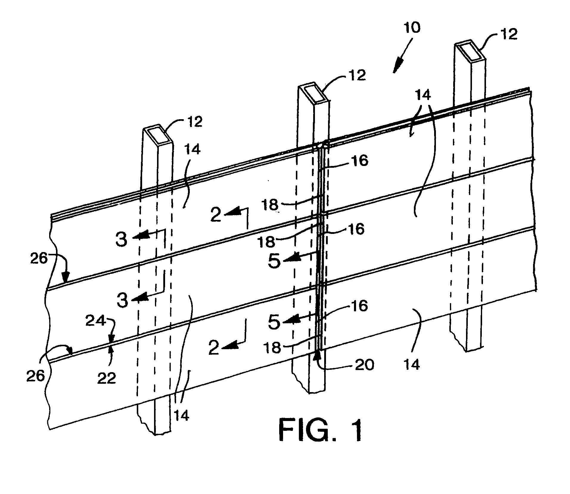
[0047]Referring to FIG. 1, there is illustrated an exterior wall structure 10 supported on a structural framework including vertical columns 12. The wall structure 10 is assembled from individual panels 14 having adjacent panel ends 16, 18 forming a vertical joint 20 and being connected along the lower and upper side edges 22, 24 to form horizontal wall joint 26.

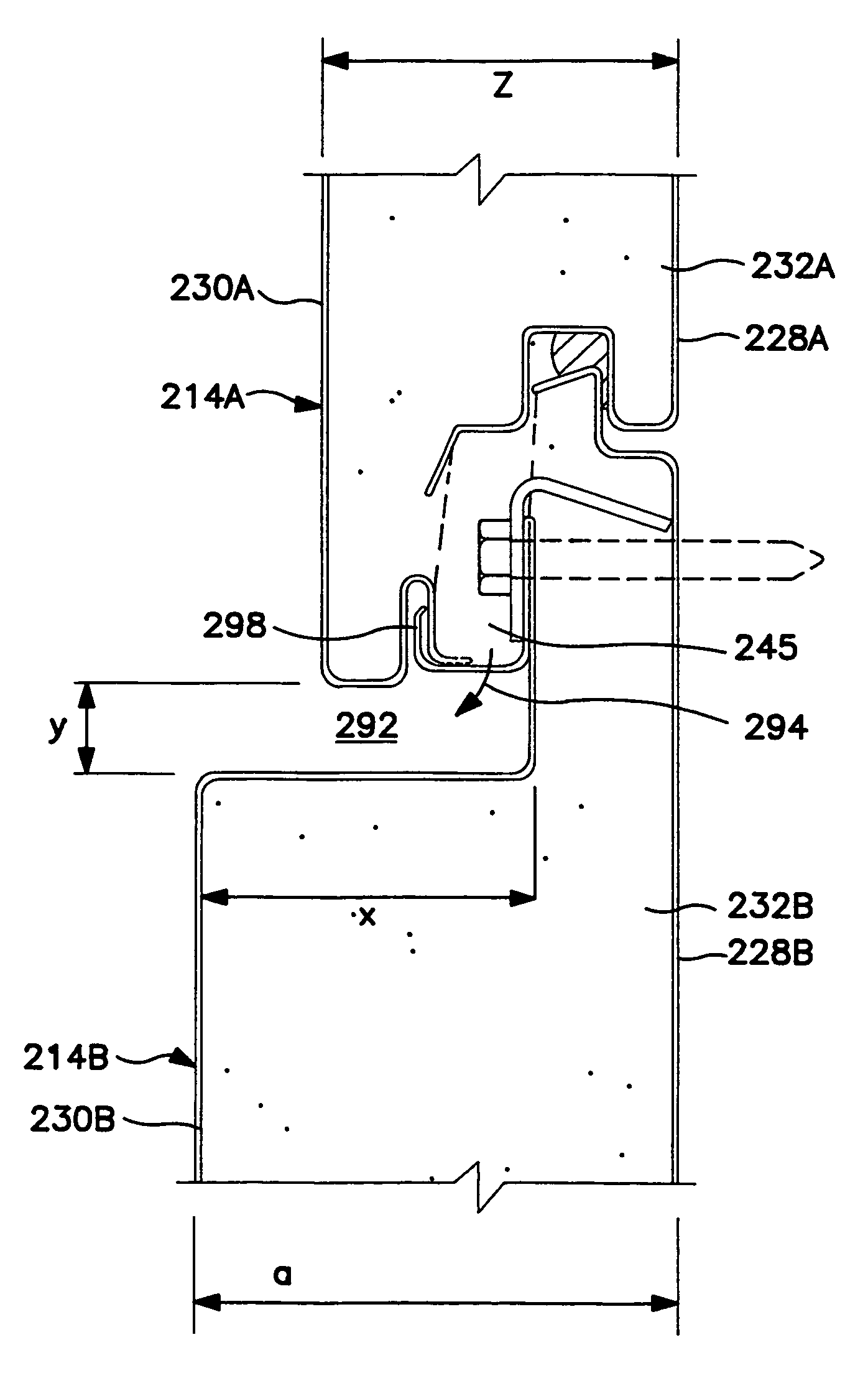
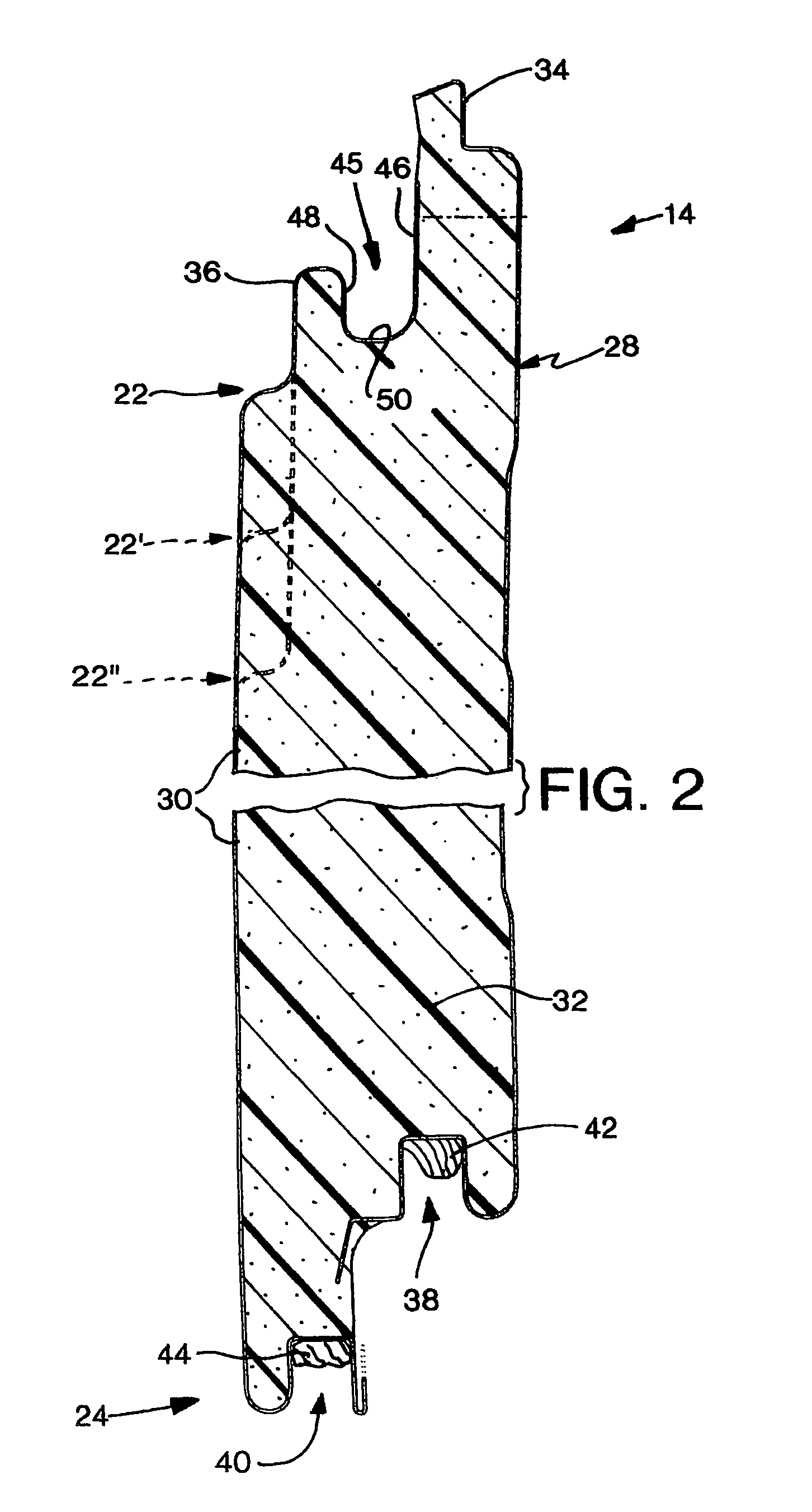
[0048]Referring to FIG. 2, the insulat...


PUM


Abstract

A horizontal joint between upper and lower building panels, as well as a building wall including such a horizontal joint, in which a liquid diverting arrangement includes a gutter with first and second ends and at least one aperture disposed between these ends. Also contemplated are a method and apparatus for forming at least two building panels, in which the panels have different reveal dimensions, and a method and apparatus for forming a building panel in which a first reveal portion is registered while a second reveal portion has been formed at a preselected distance therefrom. Further contemplated are a method and kit for customizably assembling a building wall, in which panels having different thickness dimensions can be interchangeably connected with one another, as well as a method and kit for customizably assembling a building wall, in which on or more decorative profile panels and one or more structural building wall panels can be interchangeably connected with one another.

Description

[0001]This application is a division of U.S. application Ser. No. 09 / 196,050 filed Nov. 19, 1998, now U.S. Pat. No. 6,253,511.FIELD OF THE INVENTION[0002]The present invention relates generally to joint arrangements and, more particularly, to composite, external panel joints for buildings.BACKGROUND OF THE INVENTION[0003]Generally, at a typical horizontal or vertical joint, two panels meet. Each panel typically includes one or more liners that encase a homogenous core, such as a foam core. It is also known to provide each panel with one or more “male” or “female” connecting portions, each configured to accommodate respective “female” or “male” connecting portions of the other panel.[0004]In the context of horizontal joints, an internal gutter may be included in order to accommodate liquid that has bypassed the joint. One way to drain the liquid is via the provision of vertical channels between horizontally adjacent panels. Such gutters also often typically serve as effective media f...

Claims


Application Information

Patent Timeline
IPC IPC(8): E04C2/292
CPCE04C2/292
Inventor BOYER, KEITH
Owner NCI GROUP
Why Eureka
Try Eureka