Stiffener construction having a snap-on connector, for use with a wall panel shell in a wall system

a technology of snap-on connectors and constructions, which is applied in the direction of girders, building repairs, walls, etc., can solve the problems of leg deflecting inwardly, difficult to apply pressure to the structural member, and unfavorable structural members

Inactive Publication Date: 2005-11-29
KRUEGER INT
View PDF33 Cites 37 Cited by
  • Summary
  • Abstract
  • Description
  • Claims
  • Application Information

AI Technical Summary

Benefits of technology

[0008]The structural member may be formed of a thermoplastic material in an extrusion process, and is configured to define an inner surface spaced from the outer surface to which the skin is mounted. A series of ribs extend between an inner wall and an outer wall defined by the structural member, which enables the structural member to withstand pressure applied to the structural member when mounting the skin member to the structural member. The connector member is thereafter engaged with the structural member after the structural member and the skin member are secured together, such that the outwardly extending protrusion of the connector member does not interfere with the application of pressure on the structural member to secure the structural member to the skin member.

Problems solved by technology

Further, the U-shaped construction of the structural member is not conducive to the application of high pressure to the structural member, which is required in order to establish an optimal bond between the structural member to the shell using an adhesive therebetween, since the cantilevered construction of the inner leg of the structural member results in the inner leg deflecting inwardly upon application of pressure.
And, the presence of the resilient clip member makes it difficult to apply pressure to the structural member by engagement with the outer leg of the structural member.

Method used


Image

  • Stiffener construction having a snap-on connector, for use with a wall panel shell in a wall system
  • Stiffener construction having a snap-on connector, for use with a wall panel shell in a wall system
  • Stiffener construction having a snap-on connector, for use with a wall panel shell in a wall system

Examples


Embodiment Construction

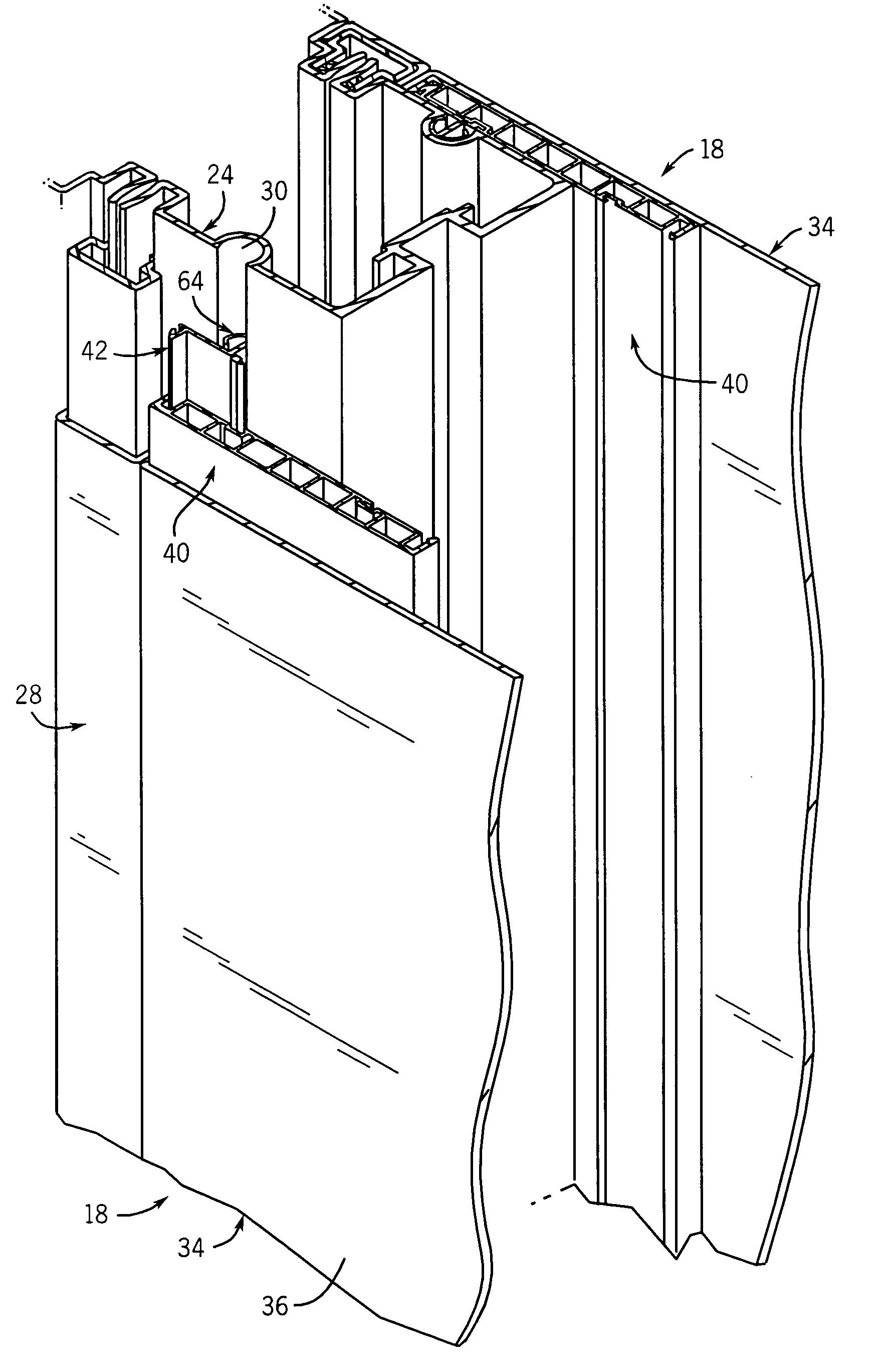
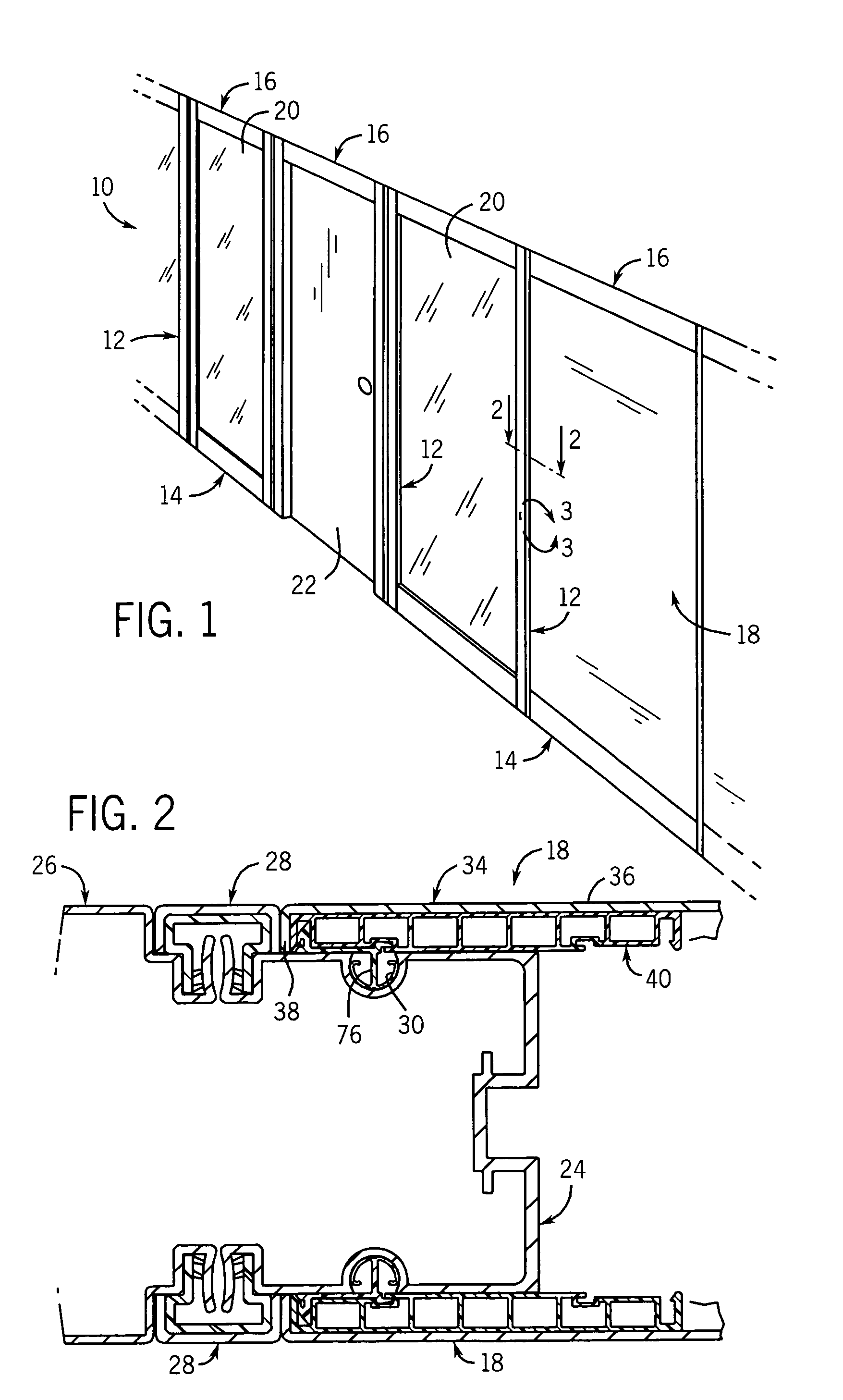
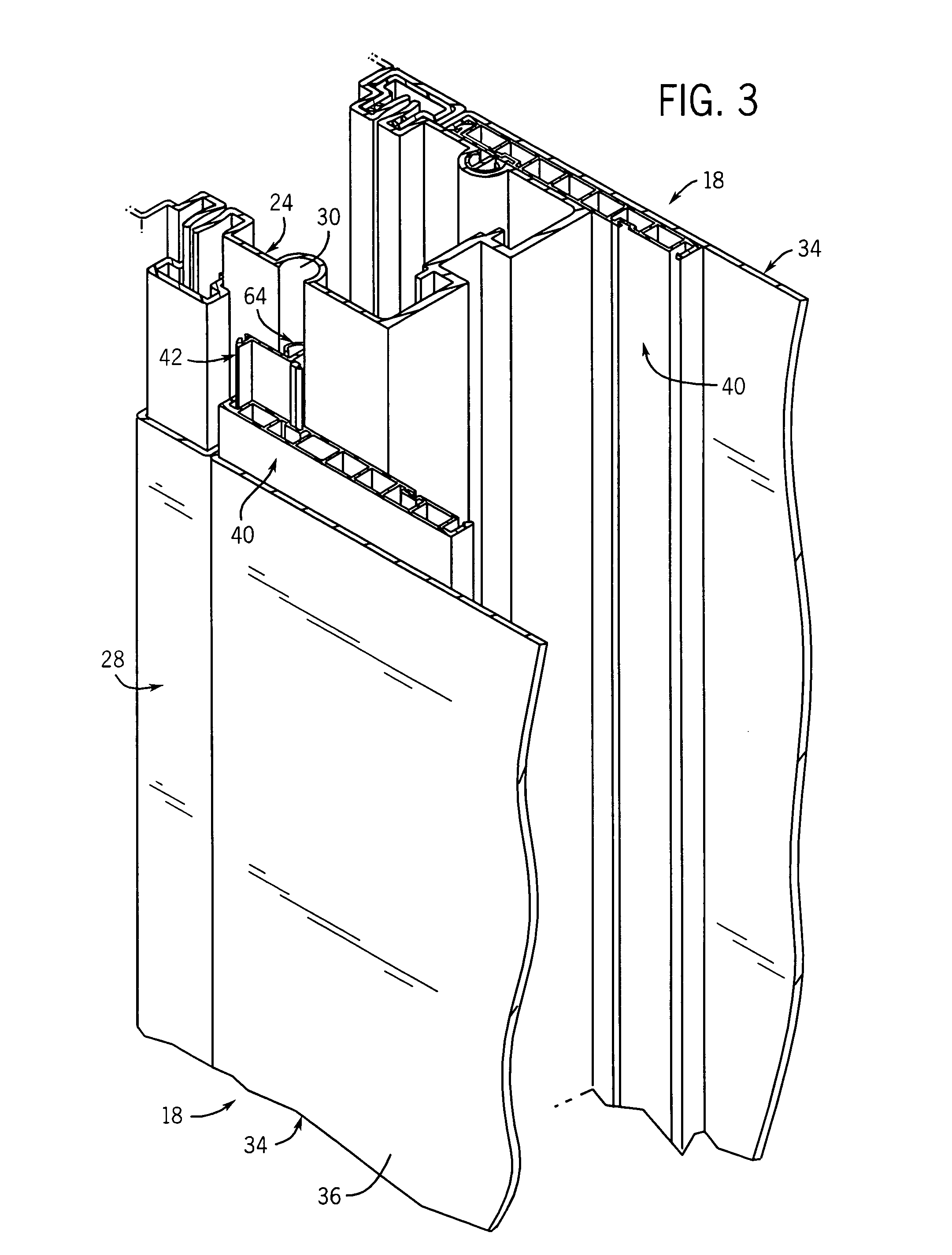
[0022]FIG. 1 illustrates a wall system 10, which includes a frame system constructed of a series of vertical members 12 which are interconnected together via lower horizontal members 14 and upper horizontal members 16. The open areas defined by frame members 12, 14 and 16 may be enclosed by opaque and sound-absorbing wall panel shells 18, glass panels 20 or other components such as a door 22. Generally, wall system 10 may be of the type that is shown and described in PCT Patent Application No. PCT / CA01 / 01856 filed Dec. 21, 2001 claiming priority from Canadian Patent Application No. 2,329,591 filed Dec. 22, 2000, now U.S. Pat. No. 6,688,056, issued Feb. 10, 2004, the disclosure of which is hereby incorporated by reference. Wall system 10 has a demountable construction, which enables the various components of wall system 10 to be shipped to an installation site in knock-down form, and then assembled on site according to a predetermined wall configuration. If desired, the components of...


PUM


Abstract

A connection system for securing a wall panel shell to a frame member. The frame member includes a groove and the shell includes a mounting member received within the groove. The shell includes a skin member secured to one or more structural members. Each mounting member is carried by a structural member, and is part of a connector that is separate from and engaged with the structural member. The connector includes a base having spaced apart engagement areas, which are received within spaced apart recesses in the structural member. The structural member defines a flat surface which facilitates application of pressure to bond the structural member and the skin member together using an adhesive. Thereafter, the connector is engaged with the structural member via a snap-on engagement arrangement, to enable the wall panel shell to be mounted to the frame member.

Description

BACKGROUND AND SUMMARY OF THE INVENTION[0001]This invention relates to a system for connecting one member to another, such as for connecting a wall panel shell to a frame in a wall system.[0002]A wall system, such as for use in an office environment, typically has a frame constructed of a series of spaced apart vertical members connected together by horizontal members that extend between adjacent vertical members. The horizontal and vertical members typically are configured to define open areas. The wall system further includes wall panels that are adapted for engagement with the frame, to enclose the open areas defined by the frame. The wall panels are typically in the form of shells having an external skin which provides the finished appearance of the wall. The shell further includes structural stiffeners along its edges, to impart a degree of rigidity to the shell and to provide a structure for mounting the shell to the frame.[0003]In a prior art construction, certain of the fram...

Claims


Application Information

Patent Timeline
Patent Type & Authority Patents(United States)
IPC IPC(8): E04B2/74
CPCE04B2/7457E04B2002/7462
Inventor KOPISH, ANDREW J.BRUGGINK, BRADLEY J.
Owner KRUEGER INT
Why Eureka
Try Eureka