System for mounting hitches to hydroformed frames

Active Publication Date: 2005-11-29
JOSEPH W WORKS
View PDF9 Cites 50 Cited by
  • Summary
  • Abstract
  • Description
  • Claims
  • Application Information

AI Technical Summary

Benefits of technology

[0011]In some cases, in order to increase the local strength of hydroformed members, the cross section of an end of one member is reduced and telescoped into another member and welded in place. The present invention takes advantage of such welded telescope joints by positioning the clamp members against such areas of reduced cross section or welds to thereby provide additional resistance to sliding of the hitch structure along the chassis members to which the structure is attached.

Problems solved by technology

With this type of assembly, an increased moment of force is induced about the rear axle thereby limiting the load which may be safely pulled by the vehicle without adversely effecting the weight distribution to the front wheels of the vehicle.
Reducing the weight distribution on the front wheels can adversely affect steering and braking of the vehicle and can also affect traction in front wheel drive vehicles.
Although fifth wheel trailer hitch assemblies provide the added advantage of allowing a vehicle to safely tow a greater weight load, the placement of the trailer hitch ball along the cargo bed of the towing vehicle can adversely affect the normal use of the cargo bed when the vehicle is not being utilized to pull a trailer.
Due to the reduced wall thickness of hydroformed frame members, warranties covering hydroformed products, such as vehicle frames, often do not allow drilling additional holes or welding to such frames, beyond those that are originally designed for by the manufacturer.
Additionally, there are limits to clamping pressures which may be applied to such hydroformed frame members particularly clamping forces applied across or perpendicular to the walls or web of the hydroformed frame members.
This presents problems in connecting conventional fifth wheel hitch structures to pickup trucks incorporating hydroformed frame members.

Method used


Image

  • System for mounting hitches to hydroformed frames
  • System for mounting hitches to hydroformed frames
  • System for mounting hitches to hydroformed frames

Examples


Embodiment Construction

[0018]As required, detailed embodiments of the present invention are disclosed herein; however, it is to be understood that the disclosed embodiments are merely exemplary of the invention, which may be embodied in various forms. Therefore, specific structural and functional details disclosed herein are not to be interpreted as limiting, but merely as a basis for the claims and as a representative basis for teaching one skilled in the art to variously employ the present invention in virtually any appropriately detailed structure.

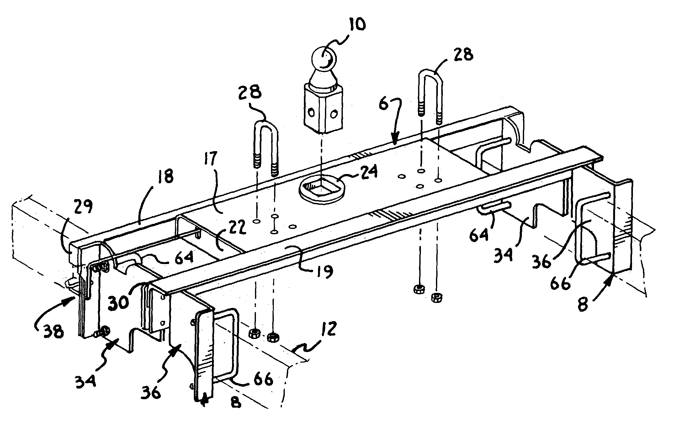
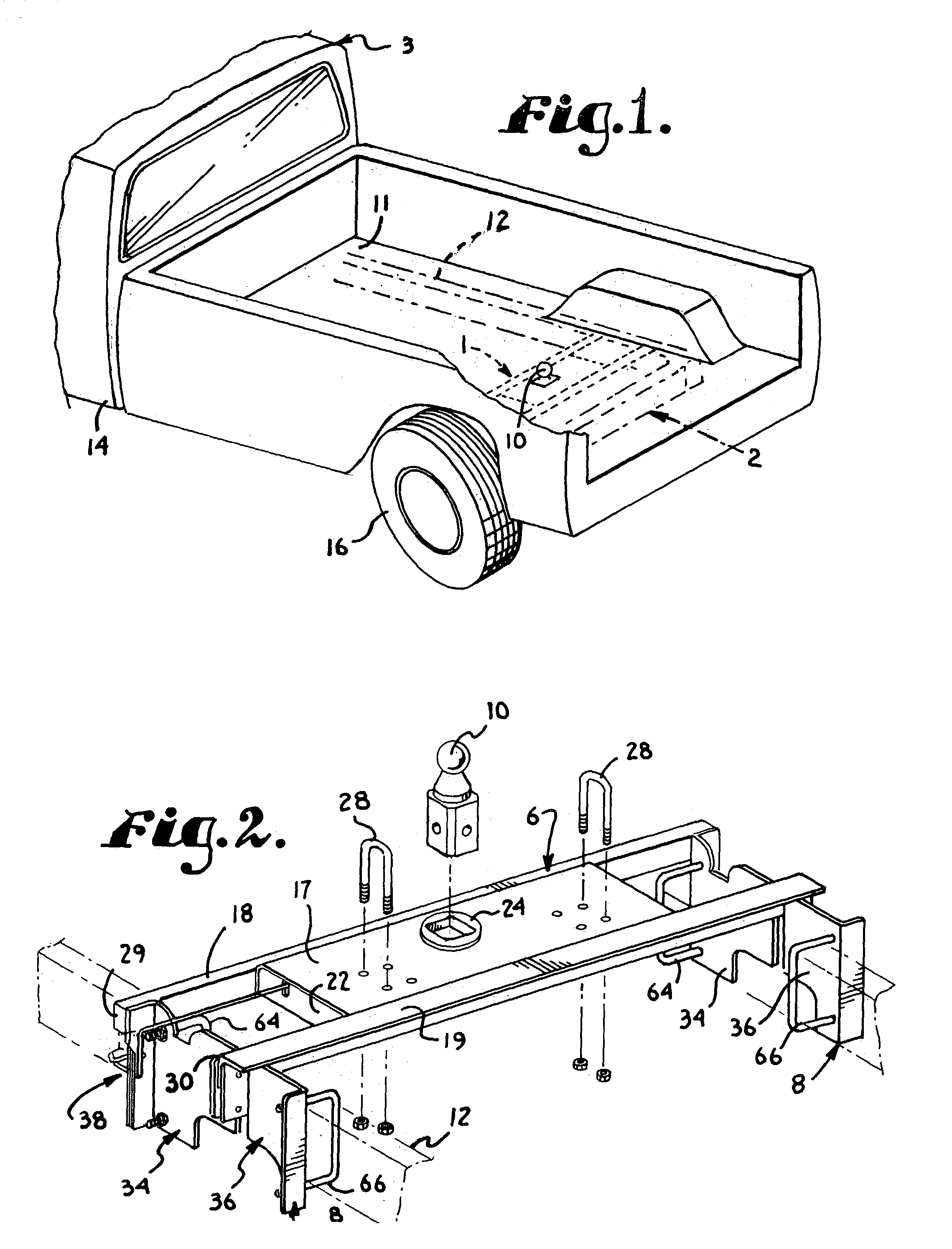
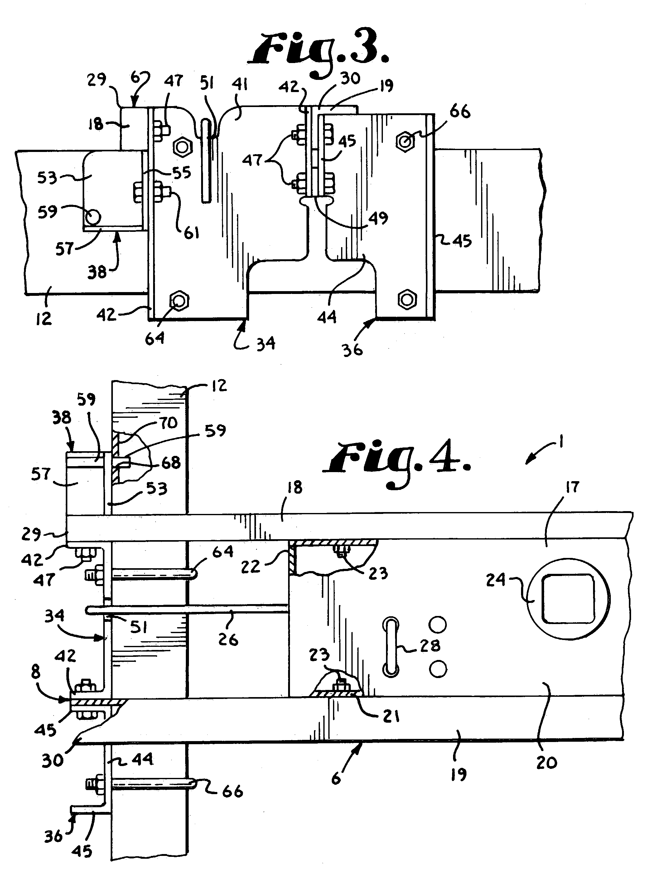
[0019]Referring to the drawings in more detail, the reference numeral 1 generally designates a fifth wheel hitch structure for a hydroformed chassis 2 of a vehicle, such as a pickup truck 3. As best seen in FIG. 2, the hitch structure 1 generally includes an upper hitch base assembly 6 and side plate assemblies 8 mounted at opposite ends of the hitch base assembly 6. The hitch base assembly 6 supports a hitch ball member 10 by which a fifth wheel trailer (not...


PUM


Abstract

A hitch structure for connection between a pair of elongated, laterally spaced hydroformed frame members of a vehicle chassis having preformed apertures formed therein. The hitch structure comprises a hitch base adapted to receive a hitch ball member, a pair of side plates connected respectively to opposite ends of said hitch base, a pin sized, positioned, and oriented on each of the side plates to enable reception of the pin member in the preformed aperture of an associated hydroformed frame member, and a pair of clamp members on each side plate to clamp the side plate with an associated frame member at such a location as to position the pin member in alignment with the associated preformed aperture to thereby secure said hitch base in transverse relation between the frame members.

Description

BACKGROUND OF THE INVENTION[0001]Conventional trailer hitches for light weight automobile and truck type vehicles normally include a hitch plate or bar which is welded adjacent the rear bumper of the vehicle or on the rear bumper of the vehicle and to which a hitch ball may be selectively secured. There are a number of conventional sizes of hitch balls which may be utilized depending upon the hitch assembly which is incorporated with the trailer that is to be towed. One shortcoming in such conventional rear end hitch assemblies is that the amount of weight which may be pulled by the vehicle is limited by the weight or force of the load which acts vertically on the hitch assembly since the hitch ball is located at a point which is spaced rearward from the rear axle of the vehicle. With this type of assembly, an increased moment of force is induced about the rear axle thereby limiting the load which may be safely pulled by the vehicle without adversely effecting the weight distributio...

Claims


Application Information

Patent Timeline
IPC IPC(8): B60D1/00B60D1/06B60D1/14B62D53/06
CPCB60D1/06B60D1/485B60D1/488B62D53/061Y10S280/901
Inventor WORKS, JOSEPH W.
Owner JOSEPH W WORKS
Why Eureka
Try Eureka