
Print system, printing method, and server

a printing system and server technology, applied in the field of printing systems, can solve the problems of high cost of a line, long communication time, and inability to obtain high-quality printing output, and achieve the effects of reducing communication burden, high quality, and large communication capacity

Inactive Publication Date: 2005-11-29
CANON KK
View PDF4 Cites 32 Cited by
  • Summary
  • Abstract
  • Description
  • Claims
  • Application Information

AI Technical Summary

Benefits of technology

The invention provides a print system that can obtain high-quality print output from an information appliance. It also reduces communication burden when downloading large data and can print detailed data even if the printer is not connected to the Internet. The system can print contents information even if the server does not have converting means for converting the information into printing data. The printing method involves inputting a print instruction, extracting second position information, forming print data, and printing the data. The printer receives the print instruction from the information appliance, issues a print request to the server, and receives the print data from the server. The technical effects of the invention include improved print quality, reduced communication burden, and improved printing flexibility.

Problems solved by technology

Similarly, as for a printer driver or the like for controlling the printer, since the printer driver with an advanced function cannot be installed, a print output of high quality cannot be obtained.
There are, consequently, problems such that a burden of a charge for the line is very large, a communicating time becomes long, an electric power consumption of the IA increases, and the like.
If there are the problems on printing from the IA as mentioned above, the troublesome operations such that the worker stores the position information such as a URL or the like of the data to be printed, the data is obtained again into a PC or the like which can be used by the printer and printed, and the like are necessary.
Since there is a limitation on use such that the printer needs to be in a state where it is connectable to the Internet as mentioned above, if the connection from the printer to the Internet is impossible due to some reasons, a print output cannot be obtained.
Therefore, if the server holding the contents information does not have the converting means for converting the contents information into the printing data, the contents information cannot be converted into the printing data.

Method used


Image

  • Print system, printing method, and server
  • Print system, printing method, and server
  • Print system, printing method, and server

Examples


first embodiment

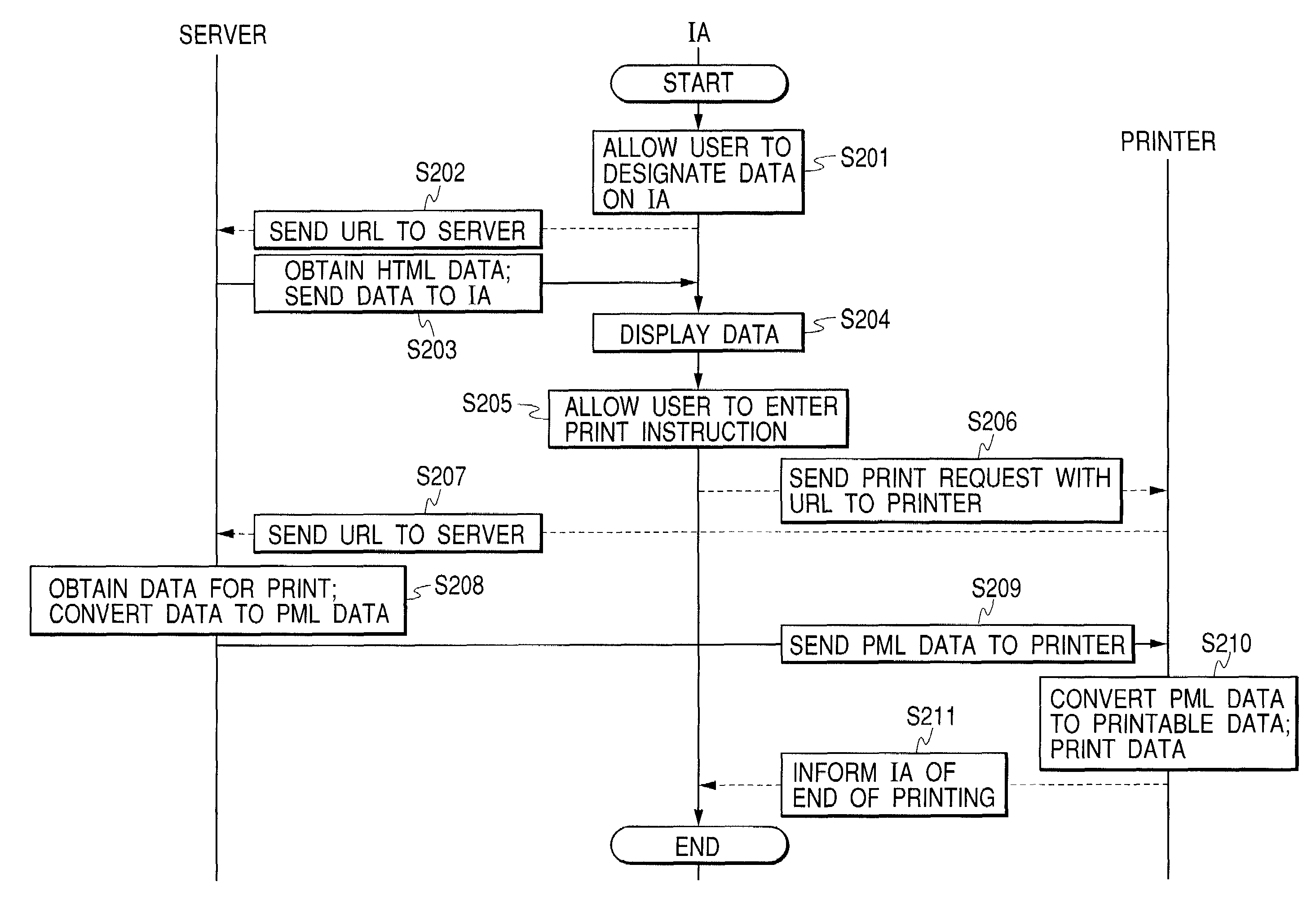
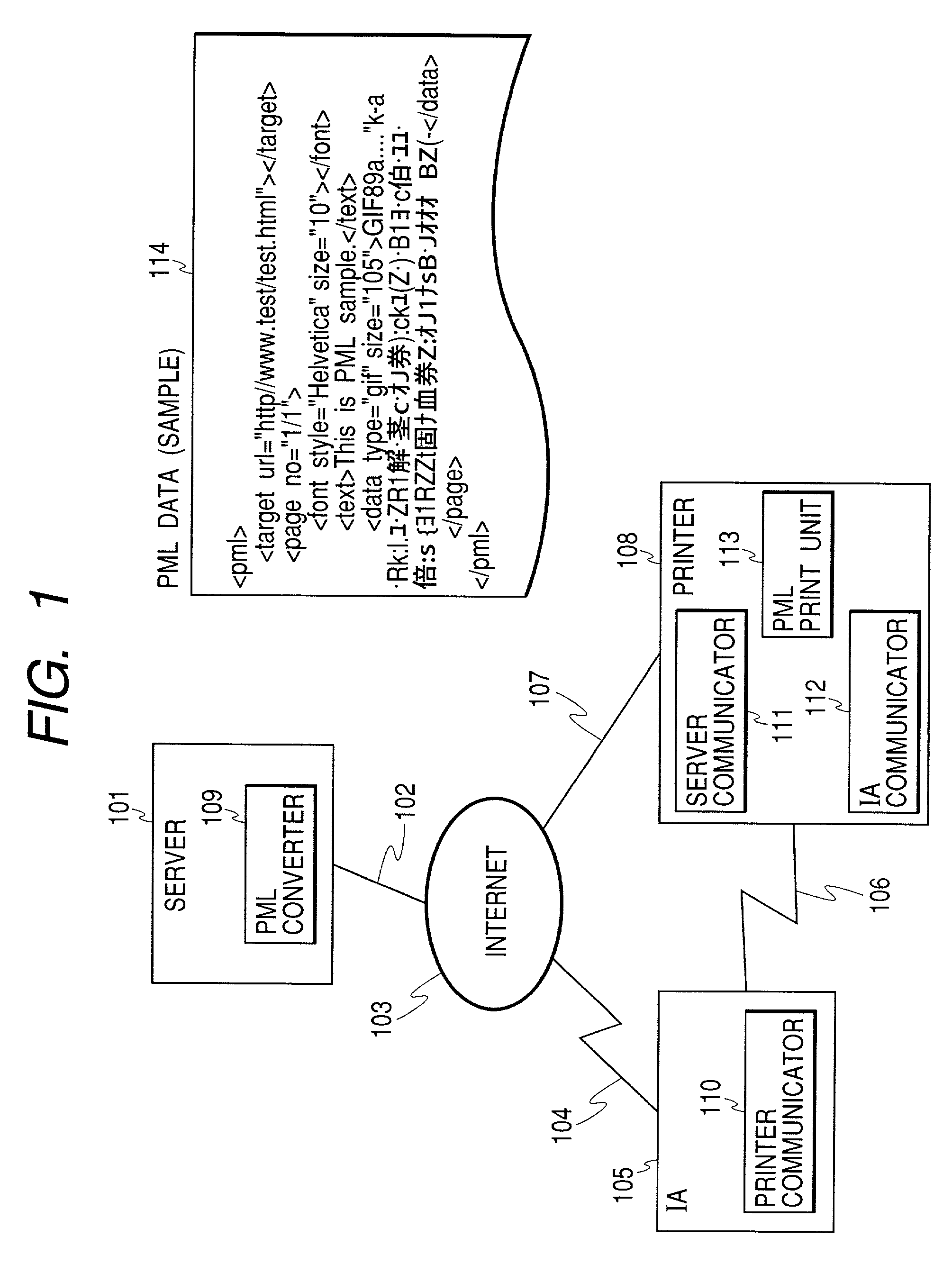
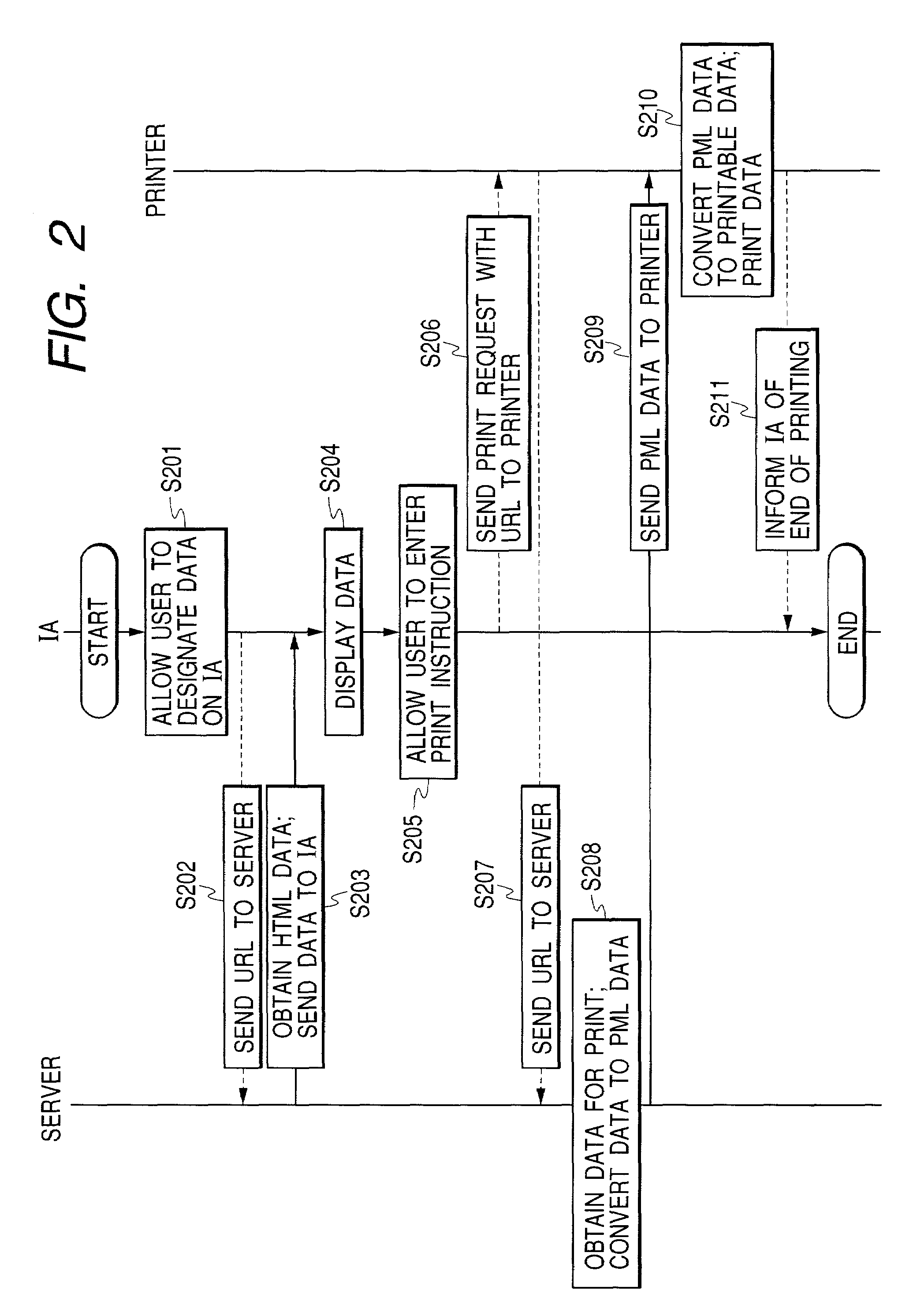
[0058]FIG. 1 is a diagram showing a construction of a print system according to the first embodiment. The print system has a construction such that an information appliance (hereinafter, simply referred to as an IA) 105, a server 101, and a printer 108 are connected through an Internet 103. The server 101 is connected to the Internet 103, functions as a WEB server, and has a PML converter 109. When a request for the print data is received from the printer 108, the PML converter 109 converts the printing data into PML (Print Markup Language) data and outputs it. If the printing data has previously been described by the PML, the PML converter 109 skips the PML conversion.

[0059]The IA 105 is an information appliance, a cellular phone, or the like and connected to the Internet 103 via a network 104 to a carrier or a provider to which the IA belongs. The IA 105 has a printer communicator 110 and can communicate with the printer 108 via a network 106 such as radio communication or the lik...

second embodiment

[0076]FIG. 3 is a diagram showing a construction of a print system according to the second embodiment. The same component elements as those in the first embodiment are designated by the same reference numerals and their descriptions are omitted here. In the second embodiment, there is shown a print output in the case where the printer 108 cannot be connected to the Internet 103 due to some reasons and the server communicator 111 is in an unusable state. At this time, the printer 108 can communicate with the IA 105 via the network 106 by using the printer communicator 110.

[0077]FIG. 4 is a diagram showing a print operating procedure for the print system in the second embodiment. First, the user operates the IA 105 and designates data such as contents or the like to be displayed to the IA 105 (S401).

[0078]The IA 105 sends the position information (hereinafter, simply referred to as “URL”) such as a designated URL or the like to the server 101 via the Internet 103 (S402). The display d...

third embodiment

[0088]FIG. 5 is a block diagram showing a construction of a print system according to the third embodiment. The same component elements as those in the first embodiment are designated by the same reference numerals and their descriptions are omitted here. A different construction will be described. That is, in the third embodiment, an access server 121 is connected to the Internet 103. The PML converter 109 is provided for the access server 121 instead of the server 101. An access server specifier 120 is provided for the printer 108.

[0089]The IA 105 obtains the contents information through the network 104. To print the obtained contents information (contents / document), the IA 105 notifies the printer 108 of the contents information by the printer communicator 110.

[0090]The printer 108 receives the contents information and print request (instruction) from the IA 105 through the network 106 by the IA communicator 112. The printer 108 issues a transmitting request for the contents info...


PUM


Abstract

There is provided a print system in which a print instruction is received from an information appliance (IA), a print request is issued to a server in response to the print instruction from the IA, and print data formed by the server is received in accordance with the print request, thereby enabling the print data to be printed from the IA.

Description

BACKGROUND OF THE INVENTION[0001]1. Field of the Invention[0002]The invention relates to a print system, a printing method, a printer, a terminal apparatus, and a server for performing a service to output data for printing such as contents, document, or the like to a printer on the basis of position information such as a URL or the like of data such as contents, document, or the like on an information appliance such as cellular phone, PDA, or the like.[0003]2. Related Background Art[0004]Hitherto, to obtain a printed matter from an information appliance (hereinafter, simply referred to as an IA), data such as contents, document, or the like held or displayed in / onto the IA is directly outputted from the IA to a printer.[0005]In the above conventional print system, however, only the data which is obtained by a small screen on the IA and by a memory of a small capacity thereof can be printed. Similarly, as for a printer driver or the like for controlling the printer, since the printer...

Claims


Application Information

Patent Timeline
Patent Type & Authority Patents(United States)
IPC IPC(8): H04L29/08
CPCH04L67/02H04L69/329
Inventor SUZUKI, HARUHISAKIMURA, TORUTAKAKU, MASAHIKOTAKAGI, EIICHIFUKUNAGA, SHINJIINOSE, TSUTOMU
Owner CANON KK
Learn More