Dispatch call server in a packet based communication network

a packet-based communication network and call server technology, applied in the field of call server, can solve problems such as the inability to arbitrate between competing transmissions

Inactive Publication Date: 2005-11-29
GOOGLE TECH HLDG LLC
View PDF12 Cites 162 Cited by
  • Summary
  • Abstract
  • Description
  • Claims
  • Application Information

AI Technical Summary

Problems solved by technology

That is, in a two-way call, only one speaker can talk at a time because a dispatch network is limited to one-way communication.
H

Method used


Image

  • Dispatch call server in a packet based communication network
  • Dispatch call server in a packet based communication network
  • Dispatch call server in a packet based communication network

Examples


Embodiment Construction

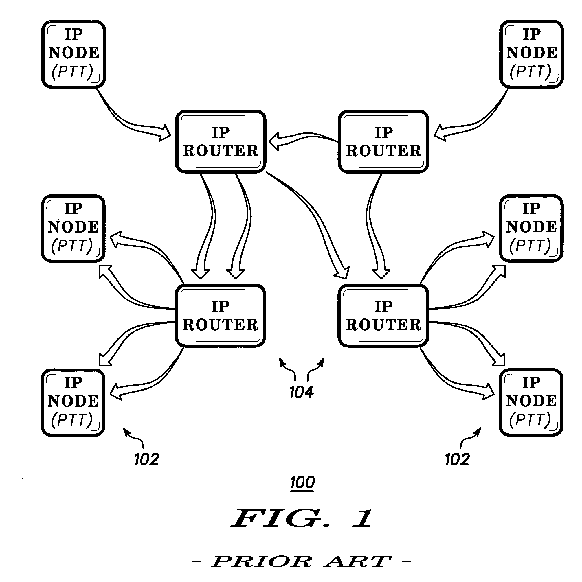
[0014]FIG. 1 is a block diagram of a conventional packet based data communication network 100 using internet protocol (IP) for data communication. The network 100 includes a plurality of hosts 102 and routers 104. The network 100 implements a dispatch communication network connecting two or more of the hosts 102 via routers 104.

[0015]Each host 102 is any computer or communication device that has full two-way access to other hosts in the network 100. The links between each host in FIG. 2 and any adjacent host are two-way links providing two-way data communication. Each host 102 has a specific local or host number that, together with a network number, forms its unique internet protocol address. In the dispatch radio network 100 of FIG. 1, each host 102 is a communication unit of the network 100. Each host 102 may be a fixed, mobile or portable radio or other device providing wireless or wireline communication with the network 100. In the illustrated embodiment of FIG. 1, the hosts 102...


PUM


Abstract

A dispatch server (206) is provided in a packet based dispatch radio network to serve as coordinator and arbitrator for dispatch group calls. Participants in a group call transmit internet protocol (IP) voice packets to the server in unicast fashion. The server receives voice packets from multiple sources (210, 216) and implements a prioritization scheme to select one source to pass on to the group via IP multicast. Various prioritization techniques are described.

Description

BACKGROUND OF THE INVENTION[0001]The present invention relates generally to networks for communication of data and voice information. More particularly, the present invention relates to a dispatch call server and its use in a packet based communication network.[0002]Dispatch communication networks including dispatch radio systems have been developed to provide two way and group calling in a radio system. Dispatch communication systems have several identifying characteristics. First, they provide talking on demand. A user who wants to communicate to another user activates a radio and begins speaking. This concept is broadly known as push to talk (PTT). Second, a dispatch communication network provides for group calling. A user can have a two-way conversation with another user or can select a group of users for a multi-party conversation. Third, dispatch radio links are one-way (also referred to as simplex or half duplex) in nature. A user cannot talk and listen at the same time. A ch...

Claims


Application Information

Patent Timeline
IPC IPC(8): H04L12/56H04W80/00
CPCH04W80/00
Inventor NEEDHAM, MICHAEL L.ROMANO, GUY G.
Owner GOOGLE TECH HLDG LLC
Why Eureka
Try Eureka