Pool cleaner storage arrangement

a technology for cleaning apparatus and storage arrangement, which is applied in the direction of gymnasiums, buildings, construction, etc., can solve the problems of affecting the swimming pool, requiring a long time to acquire and remove filters, and affecting swimmers

Inactive Publication Date: 2005-12-06
PANSINI ANDREW L
View PDF9 Cites 6 Cited by
  • Summary
  • Abstract
  • Description
  • Claims
  • Application Information

AI Technical Summary

Problems solved by technology

The pool filtering system may require a long time to acquire and remove these objects, and they may be objectionable to swimmers in the pool.
It has been observed that the random movement of the cleaning head often causes it eventually to approach and enter the receptacle that normally stores the cleaning head when it is not in use.

Method used


Image

  • Pool cleaner storage arrangement
  • Pool cleaner storage arrangement
  • Pool cleaner storage arrangement

Examples


Embodiment Construction

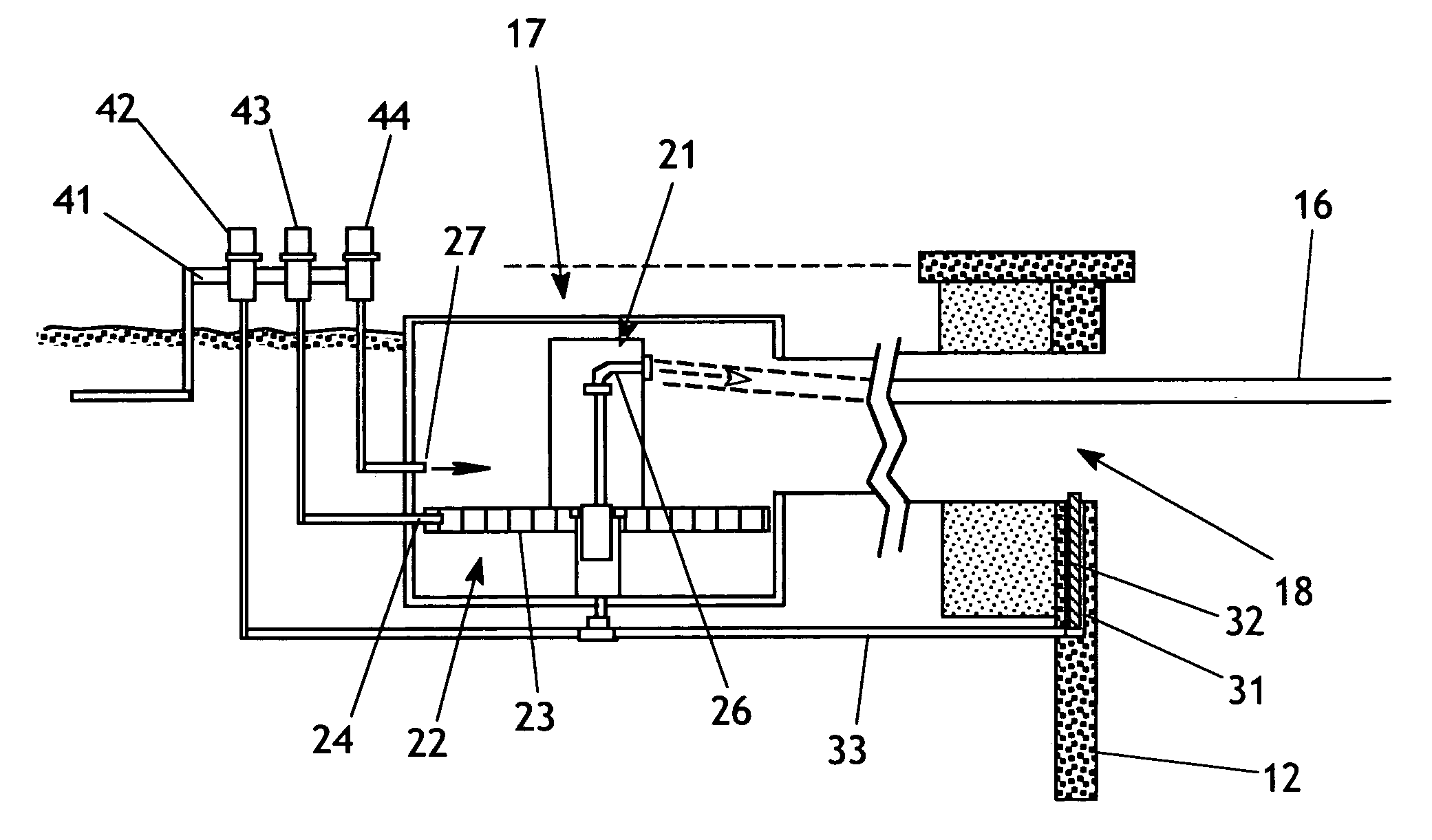
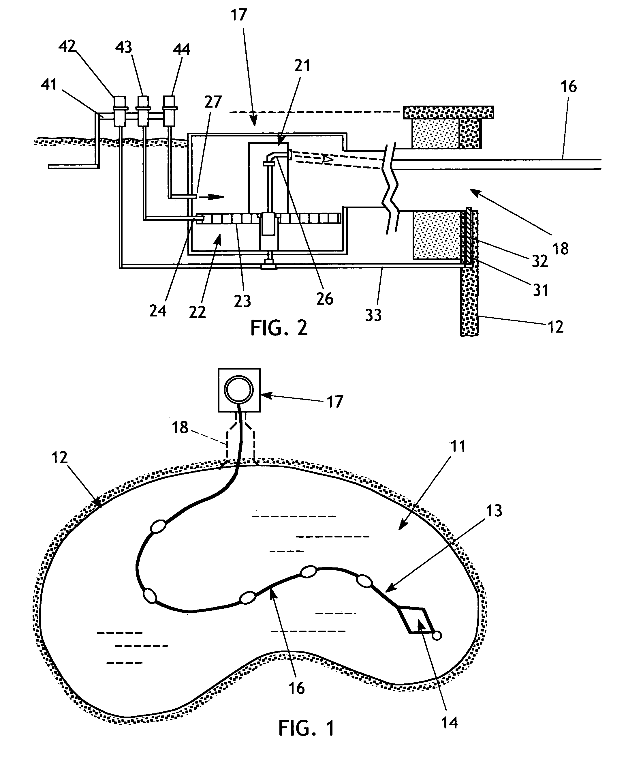
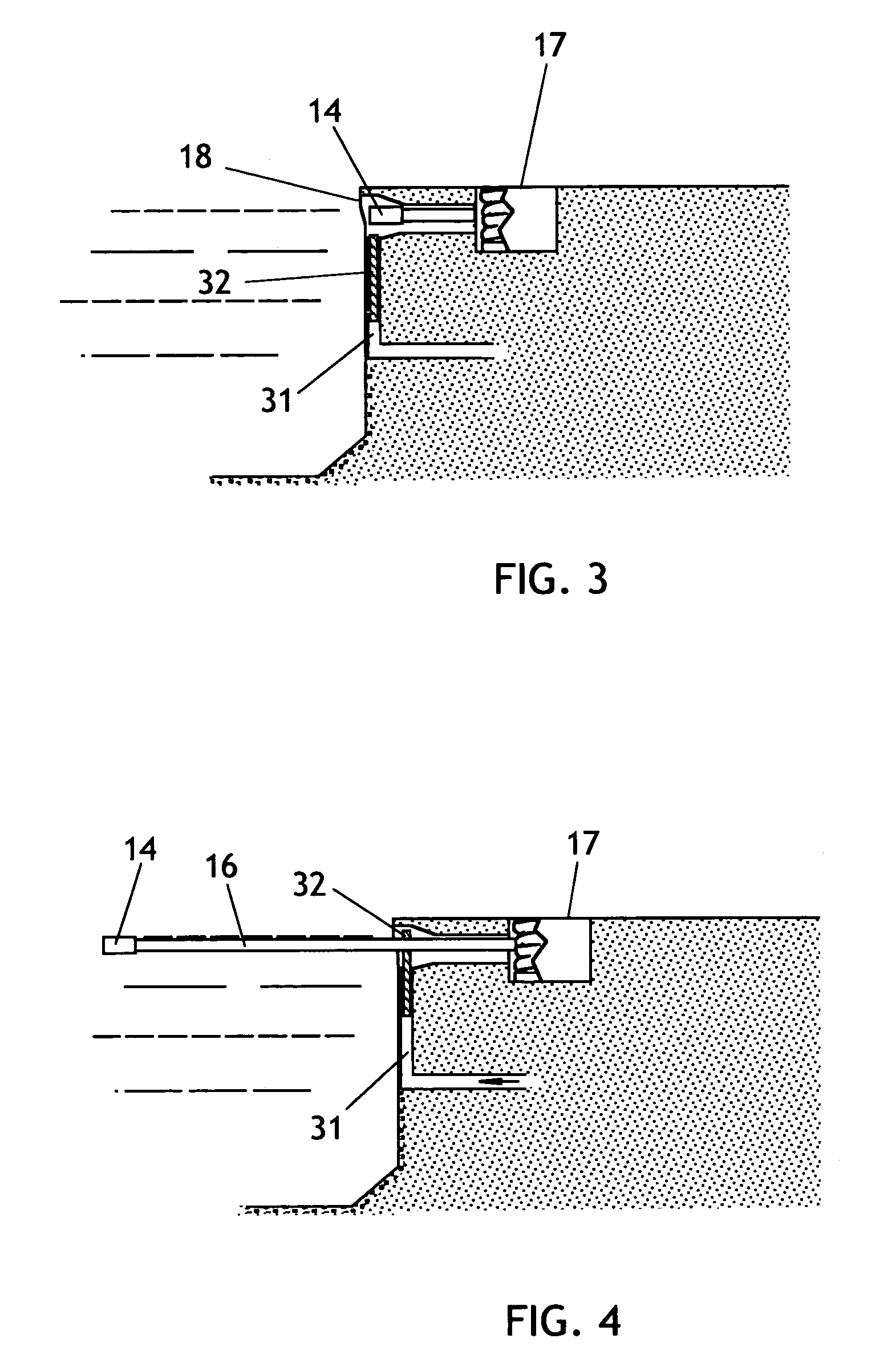
[0016]The present invention generally comprises an improved storage receptacle for an automatic swimming pool cleaning device that incorporates a cleaning head secured to a retractable hose. Although the invention will be described with reference to a prior art automatic pool cleaner that utilizes pressurized water flow supplied by a connected hose, it may be appreciated that the invention is equally effective in use with vacuum-operated systems.

[0017]With regard to FIG. 1, a typical swimming pool 11 is defined in part by a sidewall 12. A typical prior art automatic pool cleaner assembly 13 includes a cleaning head 14 attached to a hose 16 that is extendable from a reel assembly 17 disposed adjacent to the sidewall 12. The hose 16 is retractable by the reel assembly 17 to remove the hose from the pool water and draw the cleaning head 14 into a poolside storage receptacle 18 formed in an upper sidewall portion of the pool structure.

[0018]One example of an automated reel assembly 17 i...


PUM


Abstract

An improved storage receptacle for an automatic swimming pool cleaning device that incorporates a cleaning head secured to a retractable hose includes a barrier that is selectively operated to block the opening of the storage receptacle and prevent the cleaning head from entering the storage receptacle during use and becoming trapped. The barrier is a rod slidably disposed within a tube adjacent to the receptacle opening, and hydraulic action drives the rod upwardly to block the opening of the storage receptacle.

Description

CROSS-REFERENCE TO RELATED APPLICATIONS[0001]Not Applicable.FEDERALLY SPONSORED RESEARCH[0002]Not applicable.SEQUENCE LISTING, ETC ON CD[0003]Not applicable.BACKGROUND OF THE INVENTION[0004]1. Field of the Invention[0005]This invention relates to apparatus for cleaning a swimming pool and, more particularly, to an improved arrangement for storing a pool cleaning device.[0006]2. Description of Related Art[0007]There are known in the prior art various devices for cleaning the water within a swimming pool. In addition to the stationary, plumbed water circulation system that a swimming pool requires, with its pump, filter, and heater, many pools also are equipped with a system for removing floating objects from the surface of the pool. Such objects may include leaves and other tree debris, insects, garden detritus, and the like. The pool filtering system may require a long time to acquire and remove these objects, and they may be objectionable to swimmers in the pool. Although the float...

Claims


Application Information

Patent Timeline
Patent Type & Authority Patents(United States)
IPC IPC(8): E04H4/16
CPCE04H4/1681
Inventor PANSINI, ANDREW L
Owner PANSINI ANDREW L
Why Eureka
Try Eureka