Knitted slide fastener

a technology of riveting slide and fastener, which is applied in the direction of knitting, flat warp knitting machine, warp knitting, etc., to achieve the effect of stable configuration

Active Publication Date: 2005-12-06
MICROSOFT CORP +1
View PDF20 Cites 17 Cited by
  • Summary
  • Abstract
  • Description
  • Claims
  • Application Information

AI Technical Summary

Benefits of technology

[0016]Accordingly, at the fastener element attaching portion, one needle loop of the fixing chain knitting yarn made of the double structure is arranged on the upper surface of the element where the fastener element is fixed and the other needle loops are interlaced with the needle loop of the ground chain knitting yarn of the single structure configuring a wale of the corresponding base structure via a sinker loop. Therefore, the needle loops are arranged on the upper and lower surfaces of the fastener element, respectively, and further, each fastener element is pressed between the sinker loops to be fastened and fixed. As a result, extension in a longitudinal direction of the fastener element attaching portion is prevented moderately, the strength of fixture is increased, and further, the surface of the fastener element is soft so that the slidability of the slider is also improved.
[0017]In addition, in the fastener element attaching portion according to the present invention, both of the double structure and the single structure are organized by the chain knitting structure, and further, other than the weft in-laid yarn, two and more knitting yarns are not interlaced in each needle. Therefore, even if a load is given to the needle when the fastener element is pressed and strongly pulled by the knitting yarn of the double structure, there is no excess load on the needle and the folding loss and the skip of the stitch are not generated. Since the double knitting yarn and the single knitting yarn are organized by the same chain knitting structure, no excess movement is needed in the knitting machine and the operation of the knitting machine at a high speed can be realized.
[0019]Consequently, differently from the case that the side of the coupling head is solidly fixed by two different knitting yarns for fixture as the conventional case, the fixture strength is secured, and the movement of respective coupling heads when they are engaged and detached each other between the fastener elements becomes smooth. Therefore, the slidability of the slider is remarkably improved, and the slider operation can be made very light.
[0024]As a result, it is possible to effectively control an expansion degree in the longitudinal direction of the fastener tape main body and at the same time, the coupling strength can be made strong.
[0029]Consequently, the expansion of the ear portion is made less so that a figuration is stable. The effects which the present invention exerts are considerably great.

Problems solved by technology

Therefore, even if a load is given to the needle when the fastener element is pressed and strongly pulled by the knitting yarn of the double structure, there is no excess load on the needle and the folding loss and the skip of the stitch are not generated.

Method used


Image

  • Knitted slide fastener
  • Knitted slide fastener
  • Knitted slide fastener

Examples


first embodiment

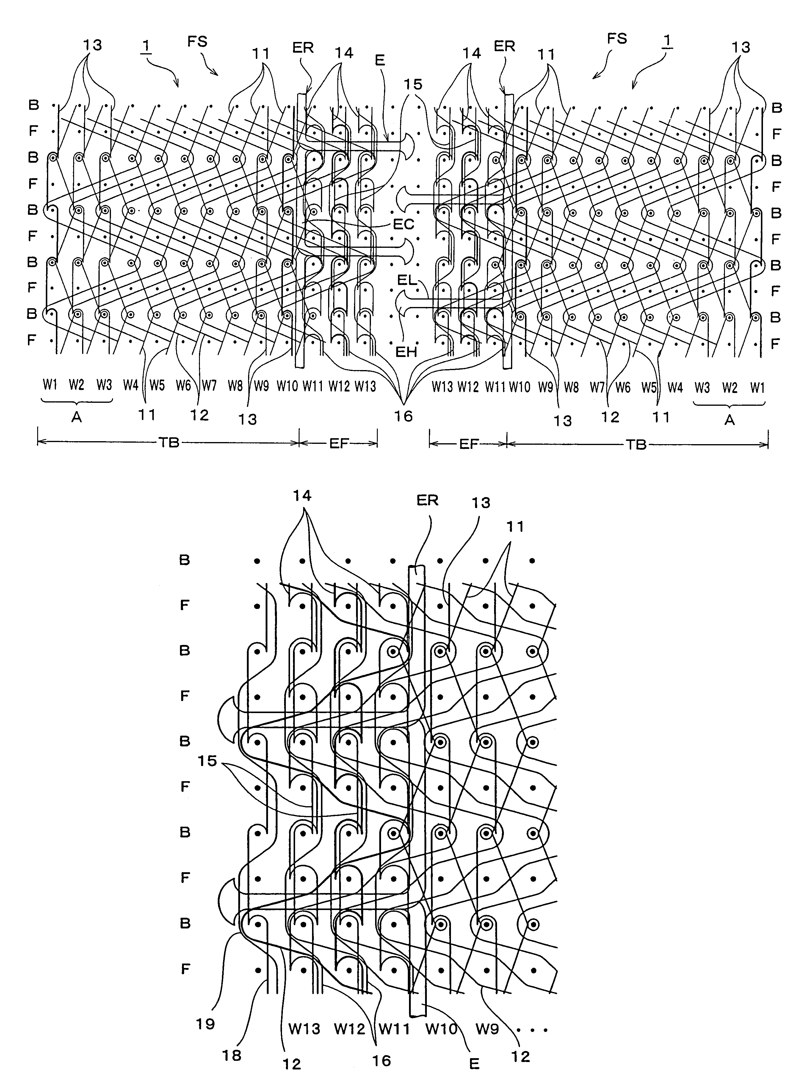
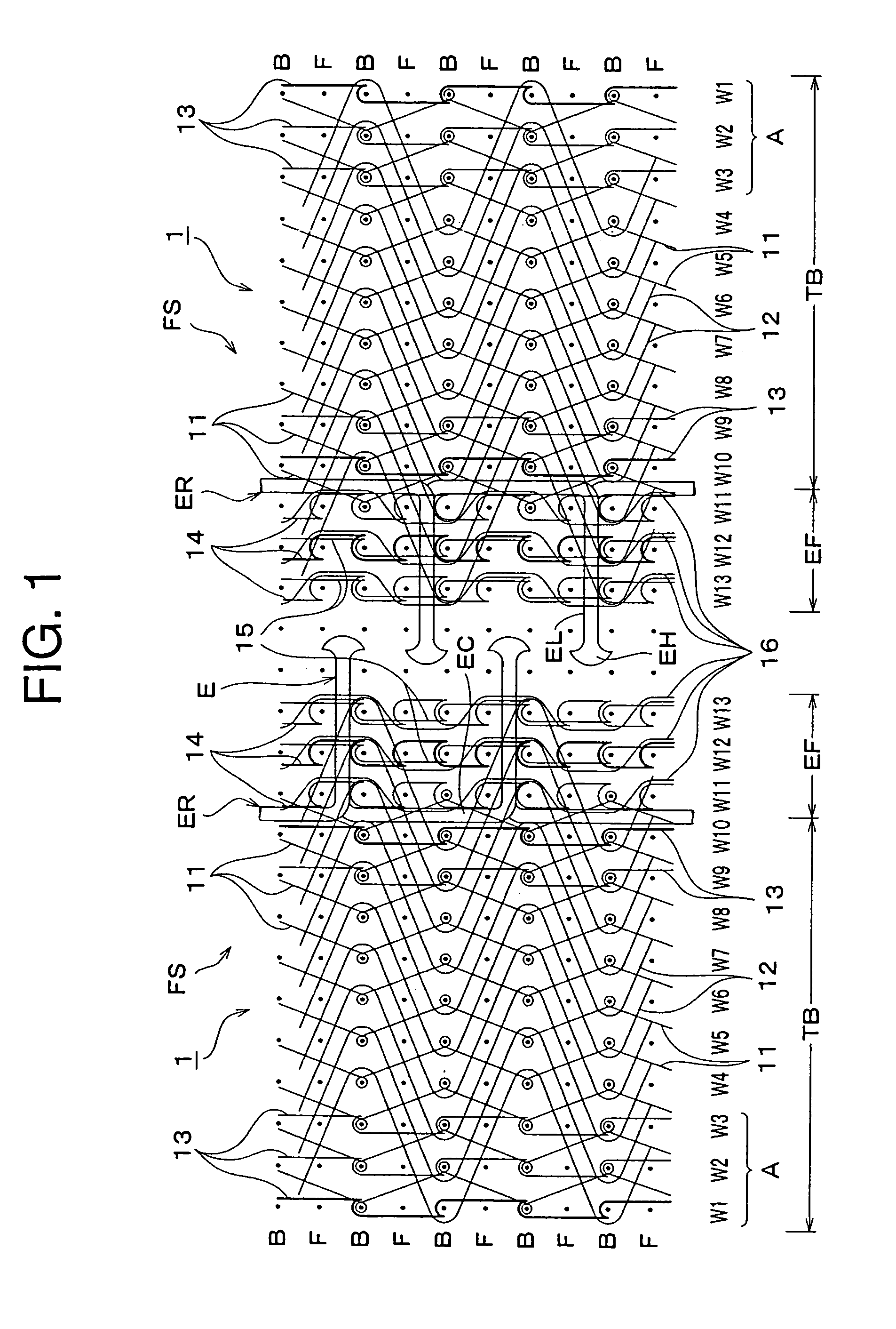
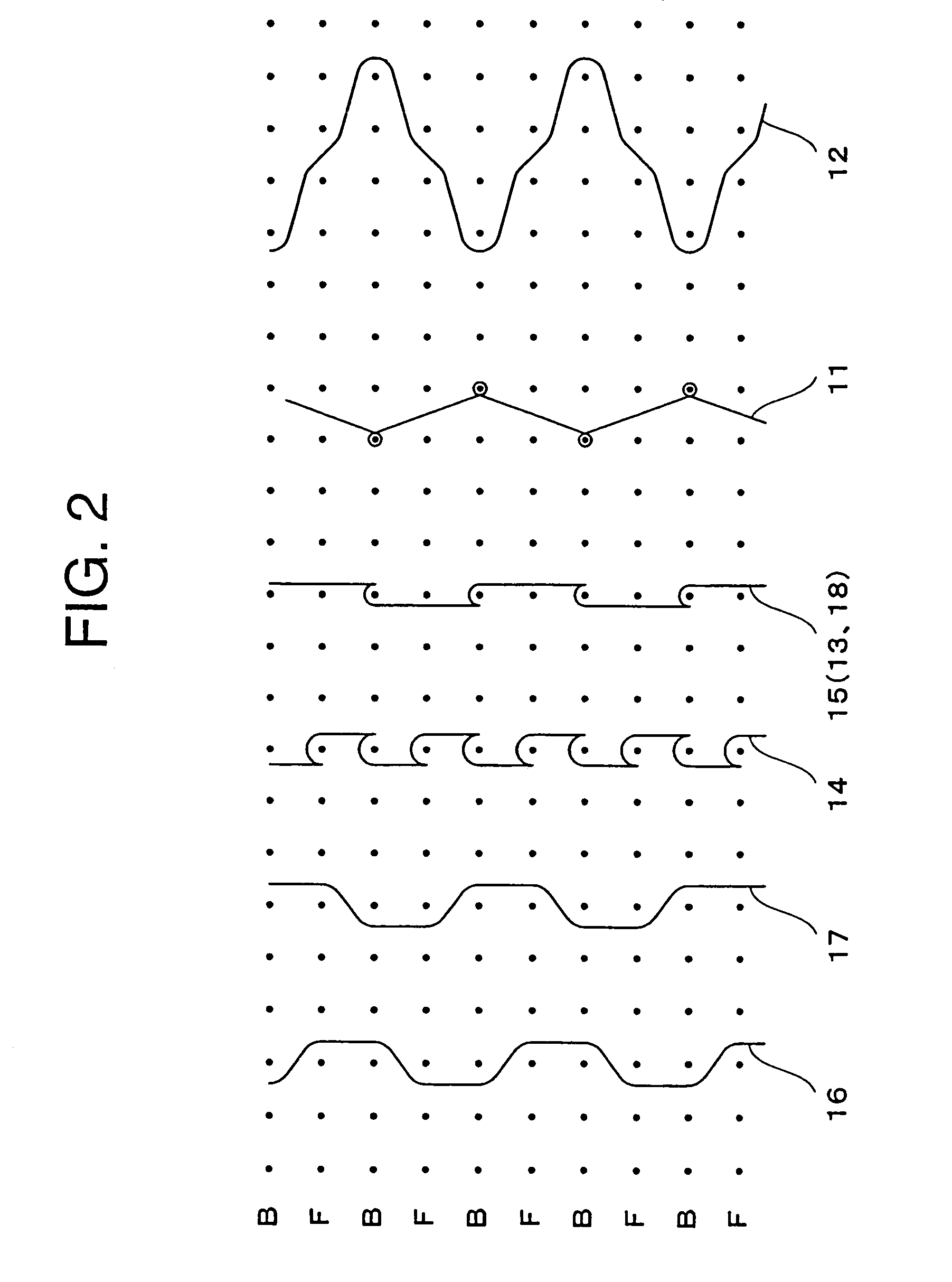
[0039]FIG. 1 is a warp knitting structure view of an entire fastener chain of a slide fastener as a first embodiment according to the present invention, and FIG. 2 shows a knitting structure for each knitting yarn.

[0040]A fastener stringer FS of the knitted slide fastener of the present invention is organized by a warp knitting machine having two rows of needle beds such as a double Russell knitting machine. Note that, in the knitting structure views shown in FIGS. 1 and 2, on a needle position, a back needle (B) and a front needle (F) are arranged for each course. A fastener tape 10 according to the present embodiment is composed of a fastener tape main body TB configured by ten wales W1 to W10, and a fastener element attaching portion EF configured by three wales W11 to W13 on which a fastener element row ER is mounted, knitted, and fixed.

[0041]As shown in FIGS. 1 and 2, a base structure of the fastener tape main body TB is configured by a ground tricot knitting yarn 11 (2-2 / 2-0 / 2...

second embodiment

[0053]FIGS. 5 and 6 show a second embodiment according to the present invention. According to this embodiment, in addition to the knitting structure of the above-described first embodiment, an ear yarn 18 composed of the ground chain knitting structure (0-1 / 0-2 / 2-2 / 2-0) of the single structure by the back needle (B) is arranged along the external side end edge of the fastener element attaching portion EF, and a warp in-laid yarn 19 (0-0 / 2-2 / 2-2 / 0-0) is inserted between the sinker loops, to which the ear yarn 18 is adjacent. By adopting such a configuration, the figuration of the external side end edge of the fastener element attaching portion EF is stabilized.

[0054]FIG. 7 shows a third embodiment according to the present invention. Although the above-described first and second embodiments target a normal slide fastener, this embodiment illustrates an example of the concealed slide fastener. This embodiment is different from the above-described first embodiment in that a direction of...


PUM


Abstract

This invention provides a knitted slide fastener, wherein at least a part of a base structure composing respective wales (W11 to W13) of a fastener element attaching portion (EF) of a fastener tape includes a ground chain knitting yarn composed of a single structure, and a partial needle loop of a fixing chain knitting yarn composes a double base structure while being interlaced only with the needle loop of the ground chain knitting yarn of the second wale (W12), the partial needle loop of a fixing chain knitting yarn to be formed on at least the second wale (W12) at a second row from the side nearest to a coupling head portion (EH) of the fastener element attaching portion (EF) among the three or more fixing chain knitting yarns of the fastener element attaching portion (EF), the knitted slide fastener being organized at a high speed with few kinds of stitches without an excess load on a needle, an element being solidly fixed.

Description

BACKGROUND OF THE INVENTION[0001]1. Field of the Invention[0002]The present invention relates to a knitted slide fastener, in which a continuous fastener element row is knitted and attached to a fastener element attaching portion at a longitudinal side edge portion of a fastener tape to be organized by a double structure at the same time of organization of the fastener tape by using a double warp knitting machine having two rows of needle beds.[0003]2. Description of the Related Art[0004]Conventionally, many knitted slide fasteners have been proposed, in which a continuous fastener element row is knitted and attached to a fastener element attaching portion at a longitudinal side edge portion of a fastener tape at the same time of organization of the fastener tape by using a double warp knitting machine having two rows of needle beds. Most of them are proposed by an applicant of the present application, and for example, they are disclosed in Japanese Patent Publication No. 3396335, J...

Claims


Application Information

Patent Timeline
Patent Type & Authority Patents(United States)
IPC IPC(8): A44B19/34D04B21/14A44B19/56
CPCA44B19/343D04B21/16D10B2501/0631C02F1/008C02F2209/005
Inventor MATSUDA, YOSHIOKATO, HIDENOBU
Owner MICROSOFT CORP
Why Eureka
Try Eureka