Heat exchanger and method of production

a technology of heat exchangers and manifolds, which is applied in the direction of indirect heat exchangers, lighting and heating apparatus, stationary conduit assemblies, etc., can solve the problems of difficult process-reliable manufacture of such heat exchangers, difficult management, and difficult connection of components, so as to reduce the thickness of sheets

Inactive Publication Date: 2005-12-06
MODINE MFG CO
View PDF19 Cites 4 Cited by
  • Summary
  • Abstract
  • Description
  • Claims
  • Application Information

AI Technical Summary

Benefits of technology

[0022]In a still further form of this aspect of the invention, the forming step includes reducing the sheet thickness at the thin portion by about ⅓ over the sheet thickness of the adjacent portions.
[0023]In yet another form of this aspect of the invention, a plurality of corners are defined by the connected joint of three of the closure pieces and the method includes, for each of the plurality of corners, (1) in at least one of the closure pieces forming a thin portion in an area to be at the connected joint defining the corner, wherein the thin portion for each corner has a sheet thickness which is less than the sheet thickness of the adjacent portions of the at least one closure piece, and (2) deforming the closure piece thin portion to form a bent edge, where the connecting step includes connecting the closure pieces to form the manifold with at least one of the bent edges abutting an end of a second of the closure pieces adjacent a generally flat section of a third of the closure pieces at each of the plurality of corners.

Problems solved by technology

Process-reliable manufacture of such heat exchangers may be difficult, however, because the connection of the components, particularly at corners formed of three parts, is difficult to manage.
Since such tube bottoms have a distinct protrusion above the heat exchanger core (generally consisting of flat tubes and corrugated ribs), such structures can require relatively significant incorporation space, which can be undesirable in instances where space is limited, such as in vehicle engine compartments.
Recycling is also hampered, because of the use of different material.
The manufacturing process in such heat exchangers can still, however, be problematic, particularly the tight solder connection, and the manufacturing cost caused by deformation of the tube ends.
However, the ends do not close the entire cross section of the collecting tubes.

Method used


Image

  • Heat exchanger and method of production
  • Heat exchanger and method of production
  • Heat exchanger and method of production

Examples


Embodiment Construction

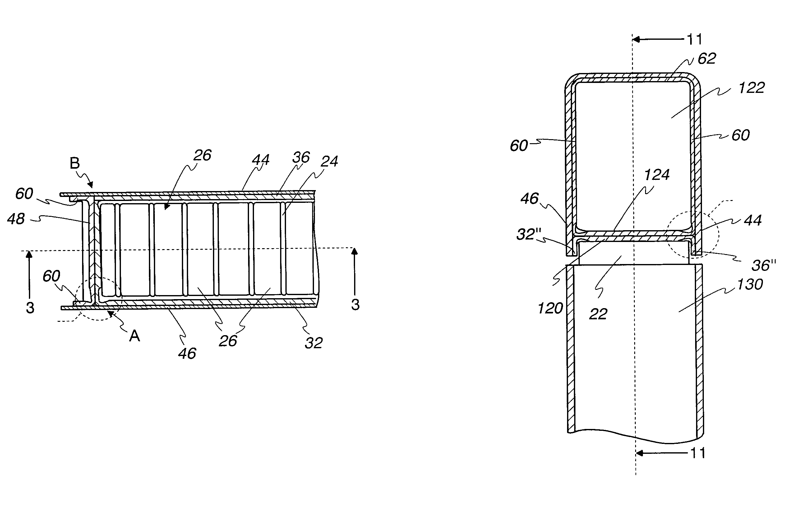
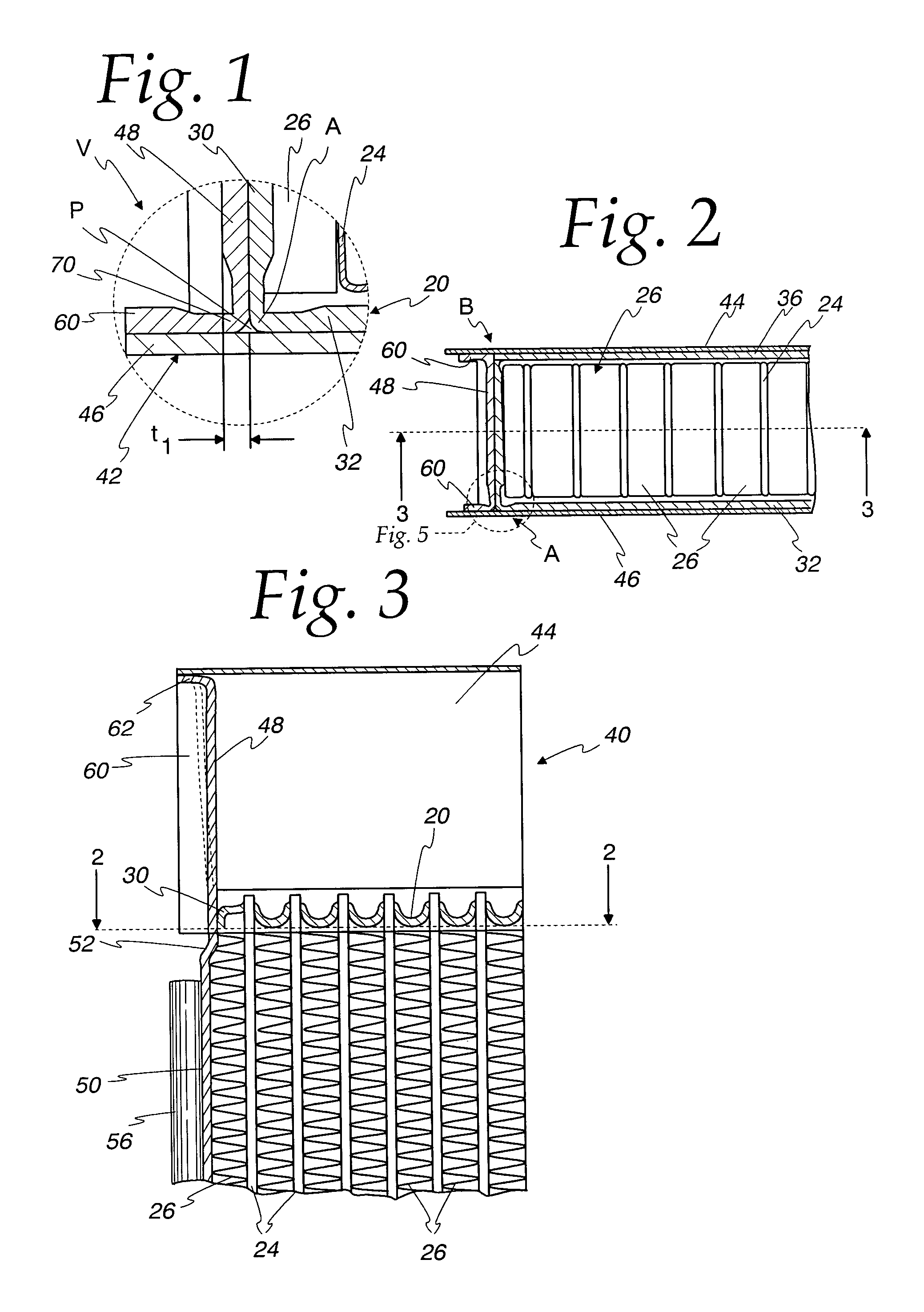
[0040]In the practical example of a heat exchanger 18 according to FIGS. 1 to 3, headers 20 (also known as header plates) may be provided such as shown in FIG. 4. Openings 22 suitable for connecting to the ends of flat tubes 24 are included in the header 20. Suitable fins 26 are provided between the tubes 24 to assist in heat exchange, such as the illustrated serpentine fins which are known in the art,

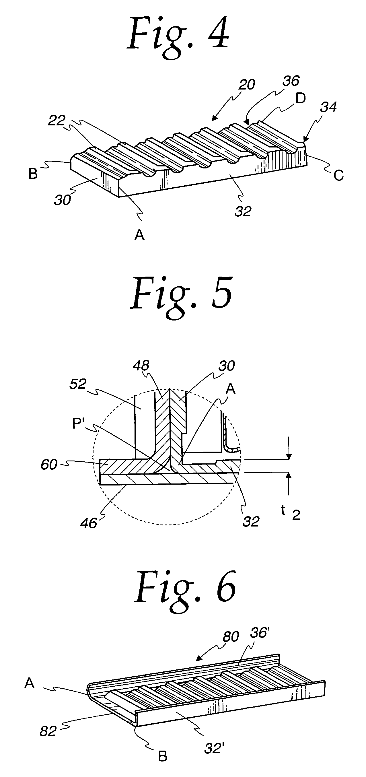
[0041]The header 20 such as illustrated in FIGS. 1–4 is generally rectangular, with four flanges 30, 32, 34, 36 oriented at generally right angles to the generally flat dimension of the header 20 (i.e., extend generally in the direction of the tubes 24) with the flanges 30–36 oriented in a box-like configuration and connected at the rectangular corners A, B, C, D of the header 20 (flanges 34, 36 are hidden in the perspective view of FIG. 4).

[0042]The header 20 is assembled as described in more detailed hereafter with other closure pieces to form a manifold 40 which defines an enclosed ...


PUM

PropertyMeasurementUnit
outer bending radiiaaaaaaaaaa
bending radiusaaaaaaaaaa
thicknessaaaaaaaaaa

Abstract

A heat exchanger having a manifold defined by a plurality of connected closure pieces. A corner of the manifold is defined by the connected joint of three closure pieces, where one closure piece has a bent edge abutting an end of a second closure piece adjacent a generally flat section of a third closure piece. The bent edge of the one closure piece adjacent the manifold corner is a bend in a thin portion of the one closure piece, where the thin portion has a sheet thickness which is less than the sheet thickness of the adjacent portions of the one closure piece. Multiple corners of the manifold can be formed in this manner by thinning the thin and bending the portion, then connecting the closure pieces using solder to form a seal in the open cross section at the corners.

Description

CROSS REFERENCE TO RELATED APPLICATION(S)[0001]Not applicable.STATEMENT REGARDING FEDERALLY SPONSORED RESEARCH OR DEVELOPMENT[0002]Not applicable.REFERENCE TO A MICROFICHE APPENDIX[0003]Not applicable.TECHNICAL FIELD[0004]The present invention is directed toward heat exchangers, and particularly toward heat exchanger manifolds having corners therein and the manufacture of such manifolds.BACKGROUND OF THE INVENTION AND TECHNICAL PROBLEMS POSED BY THE PRIOR ART[0005]Heat exchangers are known of a variety of configurations, including EP 1 004 841 A2, which has a plurality of tubes connected to a manifold which is formed of a header, closure caps and a tank closure, the individual parts being produced from solder-coated aluminum sheets, which are assembled into a heat exchanger. Process-reliable manufacture of such heat exchangers may be difficult, however, because the connection of the components, particularly at corners formed of three parts, is difficult to manage.[0006]Heat exchange...

Claims


Application Information

Patent Timeline
Patent Type & Authority Patents(United States)
IPC IPC(8): F28F9/00F28F9/02
CPCF28F9/001F28F9/0202F28F9/0224Y10T29/49373F28F2220/00Y10T29/4935
Inventor LAMICH, BERNHARDLESJAK, STANISLAUSBROST, VIKTOR
Owner MODINE MFG CO
Why Eureka
Try Eureka