
Press forming die assembly

a technology of press forming die and assembly plate, which is applied in the direction of manufacturing tools, metal-working apparatus, shaping tools, etc., can solve the problems of large amount of forming failure, and achieve the effects of preventing strain, less time, and improving product quality

Active Publication Date: 2011-11-15
HONDA MOTOR CO LTD
View PDF12 Cites 1 Cited by
  • Summary
  • Abstract
  • Description
  • Claims
  • Application Information

AI Technical Summary

Benefits of technology

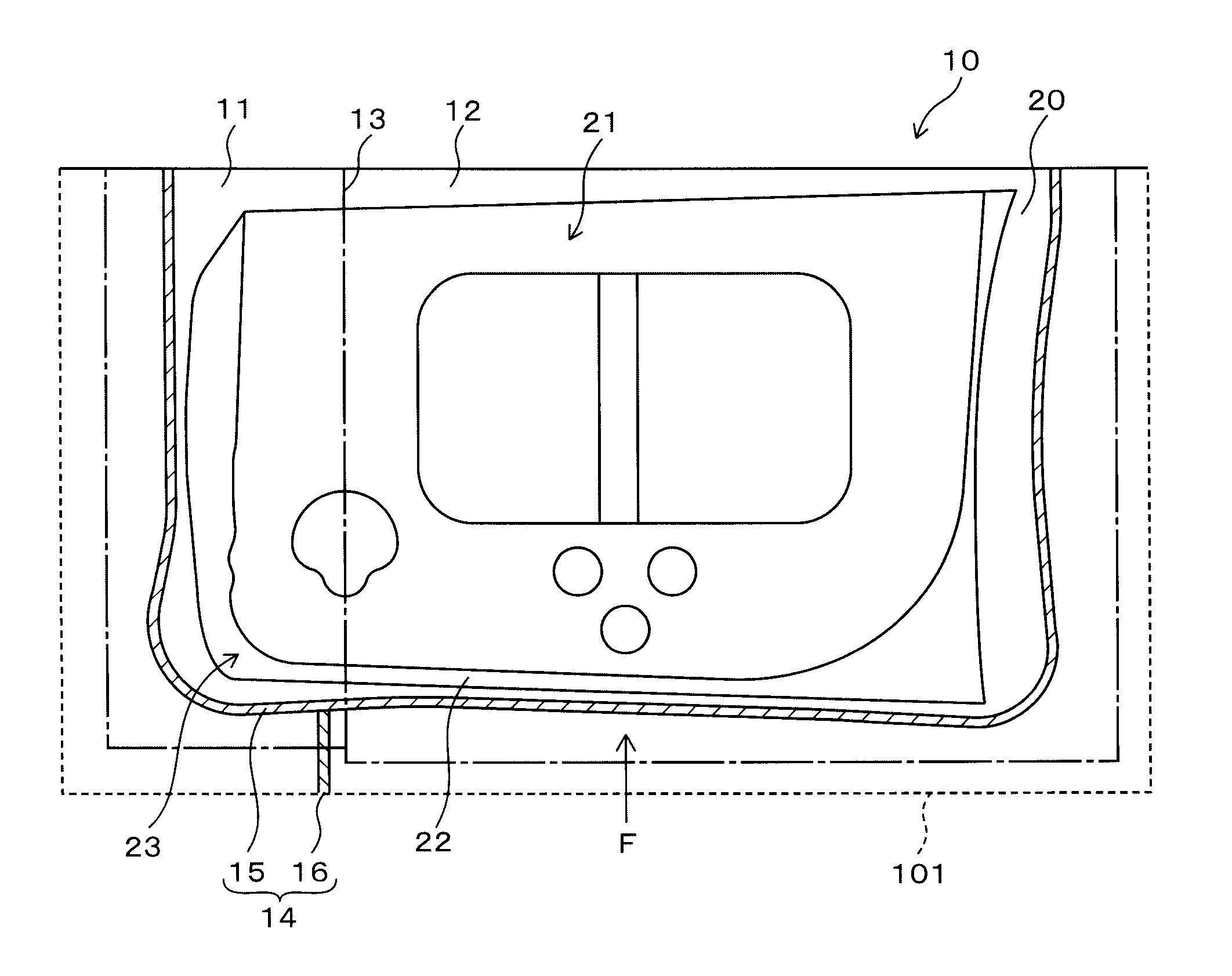
[0013]An object of the present invention is to provide a press forming die assembly in which forming failure is prevented from occurring in the vicinity of a connected portion of a thick sheet portion (or a high rigidity portion) and a thin sheet portion (or a low rigidity portion). Moreover, according to the press forming die assembly, adjustment of the die assembly requires less time, and the quality of products can be improved in commercial production.
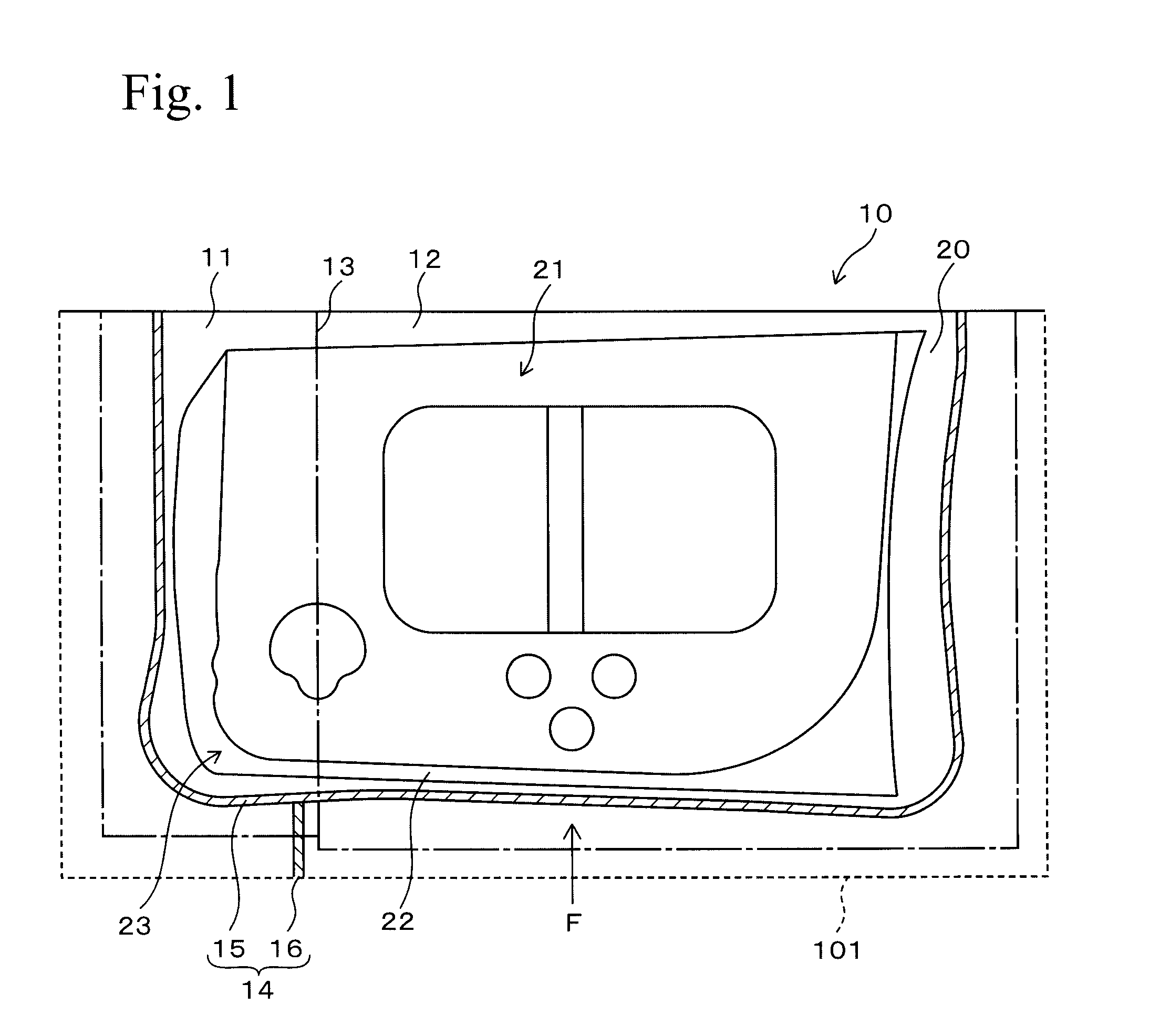
[0016]In view of the above finding, the inventors have found that the forming failure can be prevented by providing another draw bead at a thick sheet portion in a direction intersecting a conventional draw bead. The additional draw bead is provided so that strain occurring at the thick sheet portion in a shrink flange forming is not transmitted to a thin sheet portion (so that the rigidity of the thin sheet portion is sufficiently increased). In this case, the additional draw bead must be extended from the conventional draw bead toward the outside of a draw forming portion. This is because when there is a clearance between the conventional draw bead and the additional draw bead, a blank material is prevented from flowing to the draw forming portion by the clearance. As a result, the sheet thickness of a ridge line portion in a raised wall of a product surface may be decreased. The above findings are described with reference to a blank material made of sheet materials having different sheet thicknesses. In a blank material made of sheet materials having different rigidities, the portion with higher rigidity corresponds to the thick sheet portion, and the portion with lower rigidity corresponds to the thin sheet portion. Therefore, the above findings can be used for a blank material made of sheet materials having different rigidities.
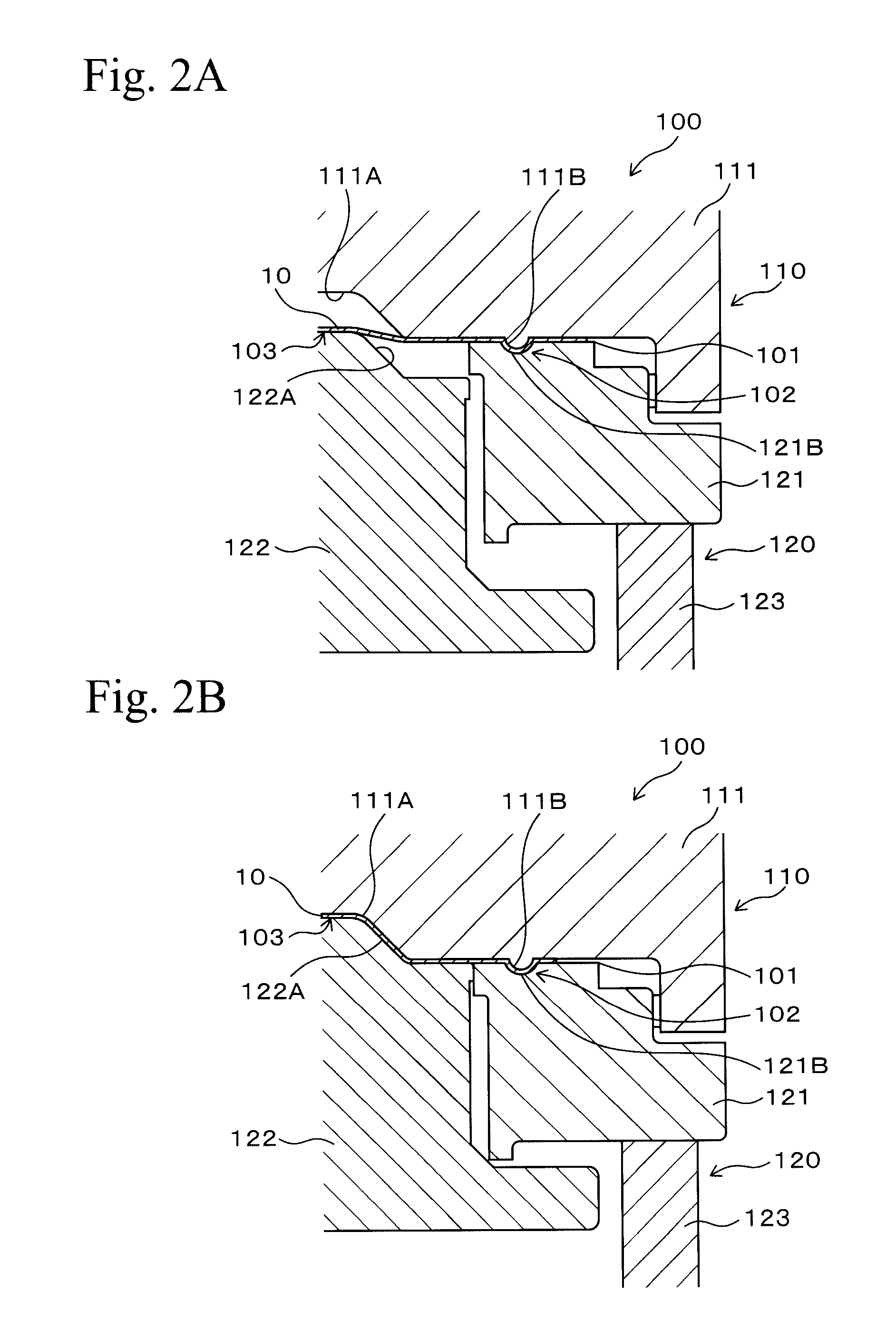
[0018]In the press forming die assembly of the present invention, the second draw bead extends from the first draw bead toward the outside of the draw forming portion in the direction intersecting the first draw bead (that is, in a direction approximately parallel to the flowing direction of the blank material to the draw forming portion). The first draw bead may be formed by a conventional technique. In general, in shrink flange forming of a flange portion of a thick sheet portion, strain occurs according to the shape of a corner of a draw forming portion. In contrast, since the second draw bead of the present invention has the above shape, such strain is not transmitted to a thin sheet portion. Therefore, rotation of the thick sheet portion (movement of the connecting line of the thick sheet portion and the thin sheet portion toward the thin sheet portion) can be prevented, whereby the thick sheet portion will not overlap with the thin sheet portion.
[0019]Accordingly, buckling wrinkling does not occur on the thin sheet portion. Therefore, when a blank material is used for an inner panel of a vehicle door, an end surface of an outer panel can be connected to an inner panel by a hemming process without deteriorating the quality of the outer panel by buckling wrinkling of the inner panel. Moreover, strain is not concentrated at the thin sheet portion, and a sufficient amount of the material flows into the draw forming portion, whereby a crack does not form at a ridge line portion in a raised wall of a product surface. Furthermore, when a material including a thick sheet portion and a thin sheet portion, which have different sheet thicknesses, is used as a blank material, a die assembly is not passed through by a sharp edge of the thick sheet portion. Therefore, wear of the die assembly can be avoided, and particles due to the wear are not generated, whereby particles are not trapped at the product surface of a panel.
[0022]According to the press forming die assembly of the present invention, the second draw bead can prevent strain from being transmitted to the thin sheet portion, the strain occurring at the thick sheet portion in shrink flange forming. Therefore, the rotation of the thick sheet portion can be prevented, and the thick sheet portion will not overlap the thin sheet portion. Accordingly, forming failure in the vicinity of the connected portion of the thick sheet portion and the thin sheet portion can be prevented. Moreover, the adjustment operation of a die assembly requires less time in trial forming, and the quality of products can be improved in commercial production.

Problems solved by technology

However, a large amount of forming failure occurred compared to the case in which only a conventional bead was used.

Method used


Image

  • Press forming die assembly
  • Press forming die assembly
  • Press forming die assembly

Examples


embodiments

[0045]Hereinafter, embodiments of the present invention will be described in detail with reference to specific embodiments. In first and second embodiments of the present invention and a comparative example, the same composite blank materials having a thick sheet portion and a thin sheet portion were used. The shape of the draw bead was changed with respect to each of the composite blank materials, and analysis of the formation was performed. The thick sheet portion had a thickness of 1.4 mm, and the thin sheet portion had a thickness of 0.7 mm. In the first embodiment, a first draw bead was formed in an arc shape in cross section, and a second draw bead was formed in a trapezoidal shape in cross section. In the second embodiment, a first draw bead was formed in an arc shape in cross section, and a second draw bead was formed in an arc shape in cross section. In the comparative example, a first draw bead was formed in an arc shape in cross section, and a second draw bead was not pro...


PUM

PropertyMeasurementUnit
thicknessaaaaaaaaaa
thicknessaaaaaaaaaa
rigidityaaaaaaaaaa

Abstract

A press forming die assembly for press forming a blank material includes a draw forming portion that the blank material flows and a draw bead for controlling the amount of the blank material flowing into the draw forming portion. A first draw bead is provided at a periphery of the draw forming portion in a direction substantially parallel to an outer peripheral shape of the draw forming portion. A second draw bead extends from the first draw bead toward the outside of the draw forming portion in a direction intersecting the first draw bead. The blank material includes a thick sheet portion having a greater thickness than the other portion or a high rigidity portion having a higher rigidity than that of the other portion. The second draw bead is provided at a portion corresponding to the thick sheet portion or the high rigidity portion of the blank material.

Description

BACKGROUND OF THE INVENTION[0001]1. Technical Field[0002]The present invention relates to a press forming die assembly including a draw bead for controlling the amount of a blank material that flows into a draw-forming portion in press forming. Specifically, the present invention relates to improvements in the shape of a draw bead used in press forming of a composite blank material that includes sheet materials having different sheet thicknesses and rigidities.[0003]2. Background Art[0004]Panels, such as door panels for vehicles, are produced by press forming a composite blank material including plural sheet materials that have different sheet thicknesses and rigidities and are integrally connected by butt-welding.[0005]A die assembly used in press forming includes a draw forming portion that has a draw forming concave portion, a draw forming convex portion, and a forming surface corresponding to a product surface of a panel. The concave portion is provided at the center of a die, a...

Claims


Application Information

Patent Timeline
Patent Type & Authority Patents(United States)
IPC IPC(8): B21D22/00
CPCB21D24/04
Inventor OKUZUMI, SHIYOUHEISAKURAI, TAKESHIMURAKAMI, SHINICHIHASEGAWA, TOMIOSERA, TAKASHI
Owner HONDA MOTOR CO LTD
Learn More