Method and apparatus for inspecting distorted patterns

a technology of distorted patterns and methods, applied in image analysis, instruments, computing, etc., can solve problems such as nonlinear spatial distortion, nonlinear spatial distortion, and problems encountered

Inactive Publication Date: 2005-12-06
COGNEX TECH & INVESTMENT
View PDF14 Cites 35 Cited by
  • Summary
  • Abstract
  • Description
  • Claims
  • Application Information

AI Technical Summary

Benefits of technology

[0010]A second embodiment of the invention provides a method for inspecting a spatially distorted pattern. A coarse alignment tool is run to approximately locate the pattern. Search tree information and the approximate location of a root sub-region found by the coarse alignment tool are used to locate a plurality of sub-regions, sequentially in an order according to the search tree information. Each of the sub-regions are small enough such that inspecting methods can reliably inspect each of the sub-regions. Each of the sub-regions is inspected.

Problems solved by technology

Complications are encountered, however, when the representation does not accurately reflect the true shape of the patterns being inspected, i.e., the representation includes a nonlinearly spatially distorted image of the pattern.
Nonlinear spatial distortions can arise from the process of taking an image of the object (e.g., perspective distortions may be caused by changes in a camera viewing angle) or from distortions in the object itself (e.g., when a credit card is laminated, an image may stretch due to melting and expansion caused by heat during lamination).
Current machine vision methods encounter difficulties in inspecting patterns with nonlinear spatial distortions.
For example, after a system has been trained on an image of a flat label, the system could not then be used to reliably inspect the same label wrapped around a curved surface, such as a bottle.
Instead, the distorted pattern will cause the system to falsely reject a part because its image comprises a nonlinearly spatially distorted pattern.

Method used


Image

  • Method and apparatus for inspecting distorted patterns
  • Method and apparatus for inspecting distorted patterns
  • Method and apparatus for inspecting distorted patterns

Examples


Embodiment Construction

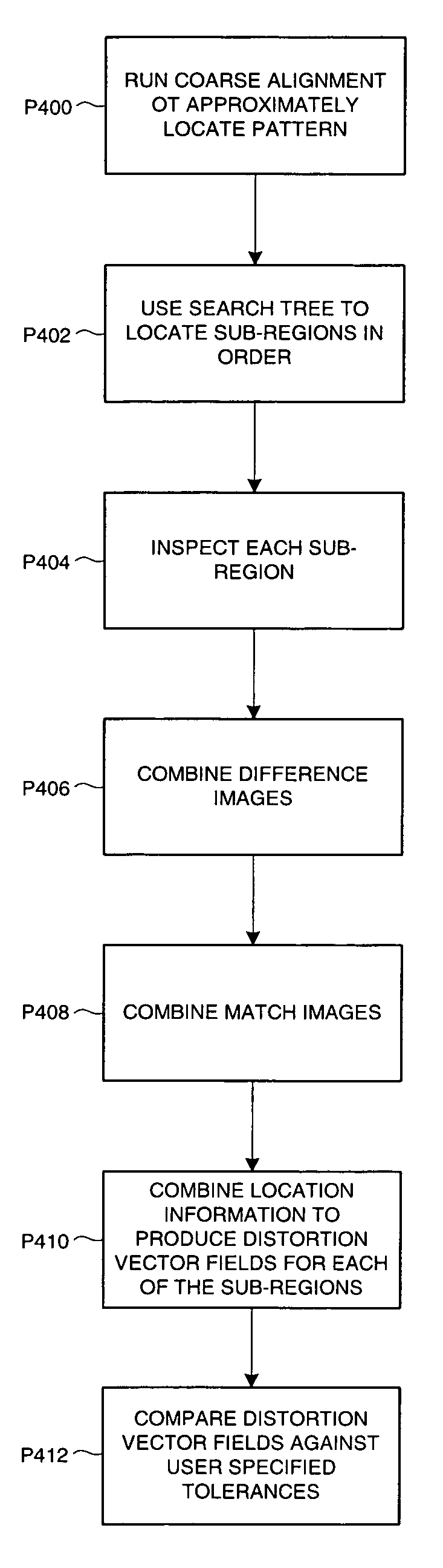
[0018]An embodiment of the invention addresses the problem of inspecting patterns having nonlinear spatial distortions by partitioning an inspection region into an array of smaller sub-regions and applying image analysis techniques over each of the sub-regions. Because the image is broken down into smaller sub-regions, those image analysis techniques need not be complex or uniquely developed (e.g., existing simple and known techniques can be used such as golden template comparison and correlation search). The illustrated system works well in situations in which there are no discontinuities in a two-dimensional spatial distortion field. An independent affine approximation is used to model the distortion field over each local sub-region. This results in a “piece-wise linear” fit to the distortion field over the full inspection region.

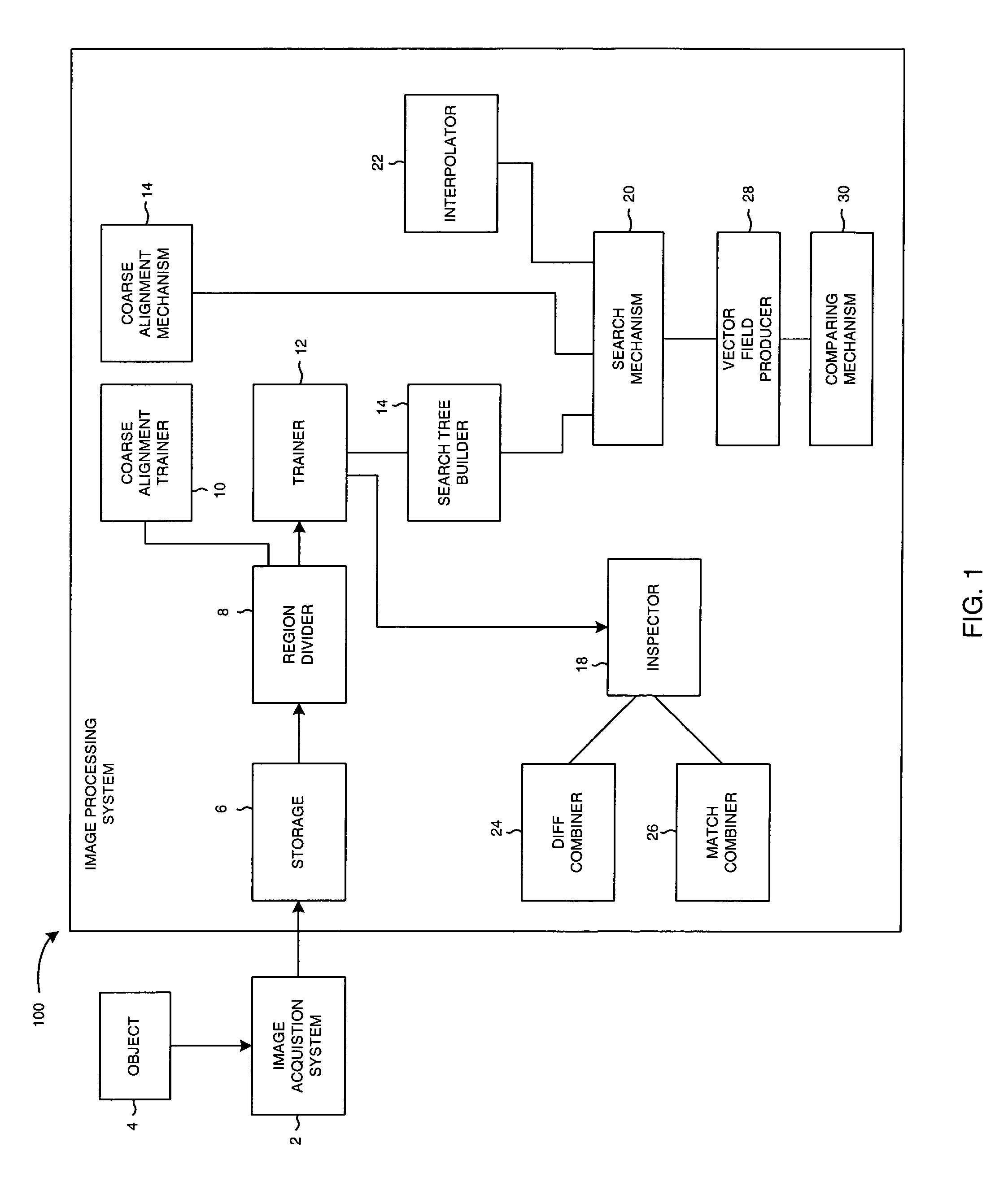
[0019]FIG. 1 is a diagram of an embodiment of the invention. Image acquisition system 2 obtains a digital image of an object 4. The image is received by ...


PUM


Abstract

An embodiment of the invention provides a method for training a system to inspect a spatially distorted pattern. A digitized image of an object, including a region of interest, is received. The region of interest is further divided in to a plurality of sub-regions. A size of each of the sub-regions is small enough such that a conventional inspecting method can reliably inspect each of the sub-regions. A search tool and an inspecting tool are trained for a respective model for each of the sub-regions. A search tree is built for determining an order for inspecting the sub-regions. A coarse alignment tool is trained for the region of interest. Another embodiment of the invention provides a method for inspecting a spatially distorted pattern. A coarse alignment tool is run to approximately locate a pattern. Search tree information and an approximate location of a root image, found by the coarse alignment tool, is used to locate sub-regions sequentially in an order according to the search tree information. Each of the sub-regions is inspected, the sub regions being small enough such that a conventional inspecting method can reliably inspect each of the sub-regions.

Description

RESERVATION OF COPYRIGHT[0001]This patent document contains material subject to copyright protection. The copyright owner has no objection to the facsimile reproduction by anyone of the patent document, as it appears in the U.S. Patent and Trademark Office patent files or records, but otherwise reserves all copyright rights whatsoever.BACKGROUND OF THE INVENTION[0002]1. Field of the Invention[0003]Aspects of the invention relate to certain machine vision systems. Other aspects of the invention relate to visually inspecting a nonlinearly spatially distorted pattern using machine vision techniques.[0004]2. Description of Background Information[0005]Machine vision systems are used to inspect numerous types of patterns on various objects. For example, golf ball manufacturers inspect the quality of printed graphical and alphanumerical patterns on golf balls. In other contexts, visual patterns of objects are inspected, including, e.g., printed matter on bottle labels, fixtured packaging, ...

Claims


Application Information

Patent Timeline
Patent Type & Authority Patents(United States)
IPC IPC(8): G06K9/00G06K9/64G06T7/00
CPCG06K9/6206G06K9/6211G06T7/0004G06V10/754G06V10/757
Inventor AKOPYAN, MIKHAILJACOBSON, LOWELLWANG, LEI
Owner COGNEX TECH & INVESTMENT
Why Eureka
Try Eureka