System and method for oscillator self-calibration using AC line frequency

a technology of self-calibration and oscillator, which is applied in the direction of pulse automatic control, electrial characteristics varying frequency control, instruments, etc., can solve the problems of oven-controlled oscillators being expensive, oscillators shifting out of their acceptable operating range, and consuming a large amount of power

Inactive Publication Date: 2005-12-06
ITRON
View PDF20 Cites 60 Cited by
  • Summary
  • Abstract
  • Description
  • Claims
  • Application Information

AI Technical Summary

Problems solved by technology

This type of oscillator, however, typically suffers from an aging effect over time that can cause the oscillator to shift out of its acceptable operating range.
However, these oven-controlled oscillators are expensive and consume a large amount of power.
If these oscillators are exposed to varying ambient temperatures over a long period of time, subtle changes occur in the crystal used in the oscillator, which cause its resonant frequency to shift.
However, in the instance of a remote mounted transmitter, it is impractical to calibrate the transmitter on an annual basis at a service depot.

Method used


Image

  • System and method for oscillator self-calibration using AC line frequency
  • System and method for oscillator self-calibration using AC line frequency

Examples


Embodiment Construction

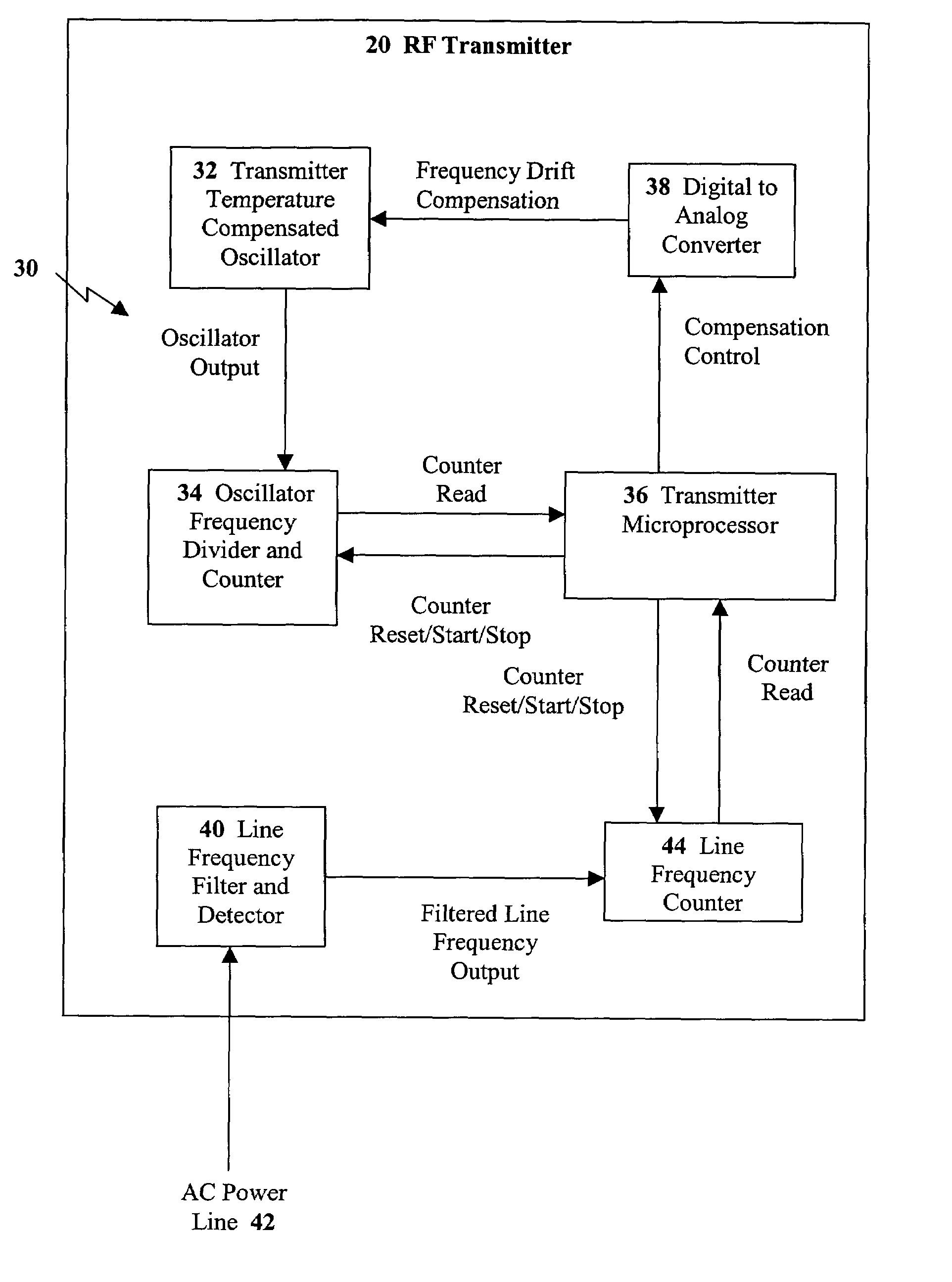
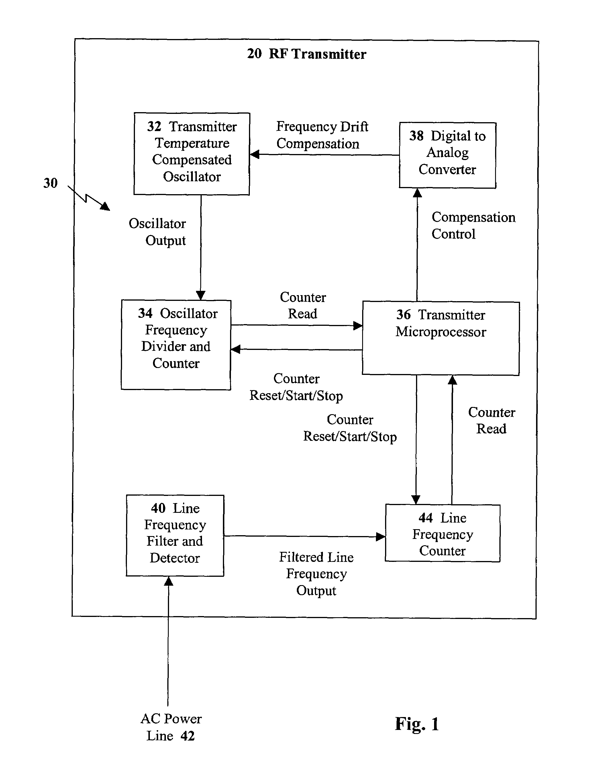
[0012]The present invention is a system and method for oscillator calibration through use of AC line frequency. The present invention eliminates the need for expensive oven-controlled oscillators and enables oscillator, self-calibration of a remotely mounted transmitter by utilizing the same AC line power source that the transmitter, itself, is powered by. In a radio frequency fixed network system, the present invention helps to simplify network design by eliminating the need for special reference transmitters and their associated costs. The system and method is preferably used for frequencies in the 952 to 957 MHz range (Multiple Address System band or MAS band), however, the system and method is suitable for any RF communication system.

[0013]FIG. 1 depicts a radio frequency transmitter 20 incorporating the oscillator self-calibration system 30 of the present invention. As shown, the self-calibration system 30 includes a reference clock, temperature-compensatable oscillator 32 (e.g...


PUM


Abstract

A self-calibrating radio frequency transmitter includes an adjustable oscillator, a first frequency counter, a second frequency counter, and a comparer. The radio frequency transmitter is powered by an AC power line, which presents a line frequency. The transmitter contains an adjustable frequency oscillator that oscillates at an oscillator frequency and has a desired operating frequency. The first frequency counter counts the oscillator frequency while the second frequency counter counts the line frequency. The comparer compares the counted oscillator frequency to the counted line frequency and produces an output representative of the difference between the counted line frequency and the counted oscillator frequency. This difference in frequency indicates a deviation in the oscillator frequency from the desired operating frequency. The output from the comparer is input to the oscillator to adjust the oscillator frequency back to the desired operating frequency.

Description

FIELD OF THE INVENTION[0001]The present invention relates to frequency drift compensation of radio frequency transmitter reference clock oscillators and, more particularly, to frequency drift compensation of these oscillators through use of existing AC line frequency.BACKGROUND OF THE INVENTION[0002]Radio frequency transmitters need to maintain a very high frequency accuracy over their life span to meet the requirements of the Federal Communications Commission (FCC) and to operate with narrow frequency channels. In outdoor applications, this frequency accuracy must be maintained over a wide temperature range. The accuracy of the transmit frequency is directly related to the accuracy of the oscillator used in the transmitter. It is, therefore, imperative that the transmitter have a very stable and accurate oscillator.[0003]To accomplish this stability and accuracy a temperature compensated oscillator is usually used. This type of oscillator, however, typically suffers from an aging e...

Claims


Application Information

Patent Timeline
Patent Type & Authority Patents(United States)
IPC IPC(8): G01R35/00G06F19/00H03L7/085H03L7/181
CPCH03L7/085H03L7/181
Inventor CAHILL-O'BRIEN, BARRYCORNWALL, MARK K.
Owner ITRON
Why Eureka
Try Eureka