Liquid crystal display device and drive method therefor

a display device and liquid crystal technology, applied in the direction of electric digital data processing, instruments, computing, etc., can solve the problems of difficult to prevent the frequency of liquid crystal driving noise, the device is becoming thinner, and the recognition performance of the capacitive touch sensor is affected, so as to prevent the effect of reducing the recognition performance of the capacitive touch sensor

Inactive Publication Date: 2013-10-31
SHARP KK
View PDF5 Cites 13 Cited by
  • Summary
  • Abstract
  • Description
  • Claims
  • Application Information

AI Technical Summary

Benefits of technology

[0025]According to a liquid crystal display device in accordance with the present invention, correction is made so that the frequency at which the liquid crystal panel is driven and the frequency at which the capacitive touch sensor is scanned have the same variation. Therefore, even in a case where the frequency of the liquid crystal driving noise shifts, the liquid crystal driving noise is scarcely mixed into the sensing. This makes it possible to avoid the mixing of the liquid crystal noise into the sensing, and thus makes it possible to prevent a decrease in recognition performance of the capacitive touch sensor caused by the mixing-in of the liquid crystal driving noise.

Problems solved by technology

In a case where the liquid crystal driving noise is mixed into the sensing, a decrease in recognition performance of a touch panel is caused.
This makes it difficult to prevent the frequency of the liquid crystal driving noise and the noise frequency sensed by the touch panel from overlapping each other.
However, since display devices are becoming thinner nowadays, it is difficult to extend the gap between the touch panel and a liquid crystal panel, which is the source of the liquid crystal driving noise.
Furthermore, newly providing the shield layer may increase costs.

Method used


Image

  • Liquid crystal display device and drive method therefor
  • Liquid crystal display device and drive method therefor
  • Liquid crystal display device and drive method therefor

Examples


modified example

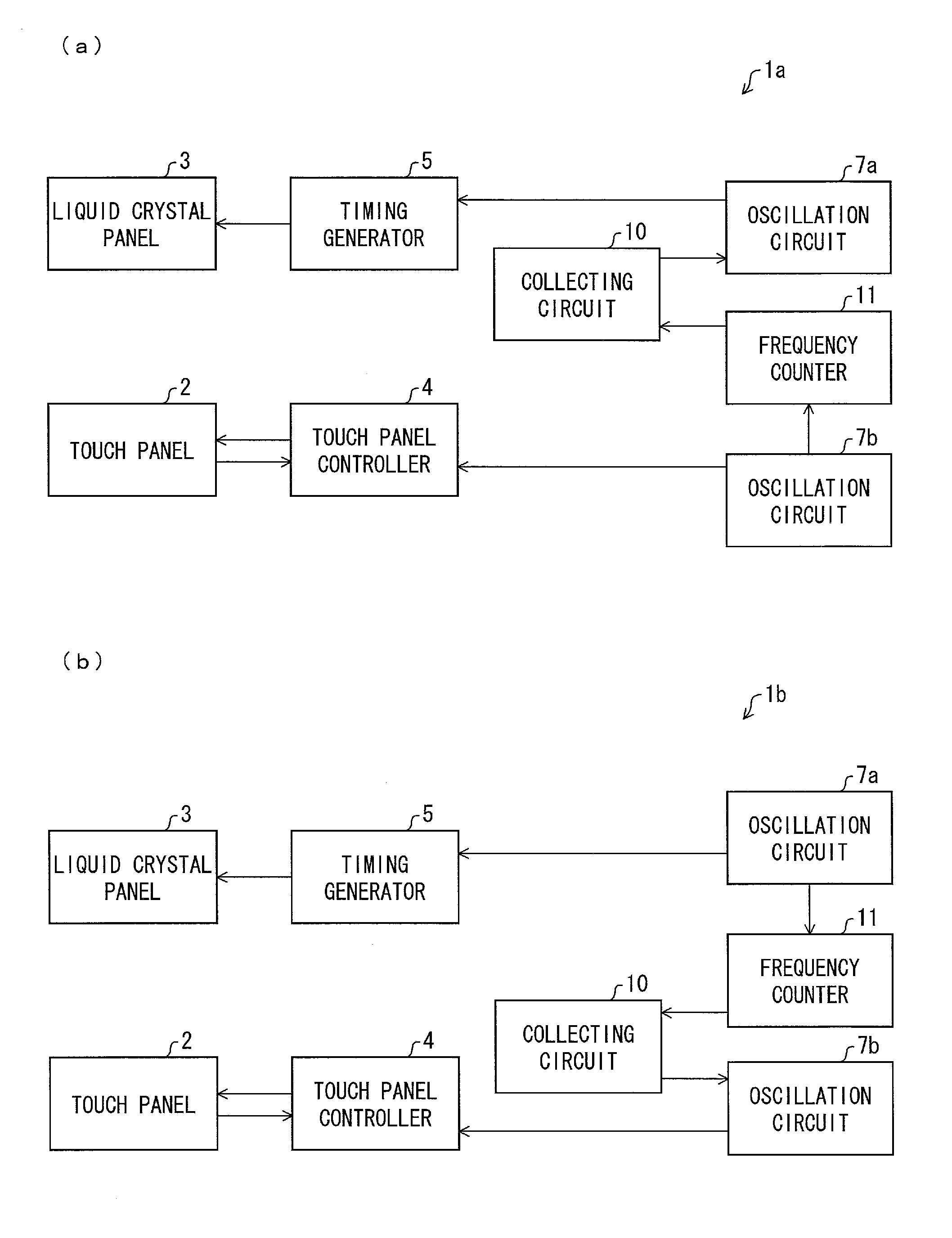
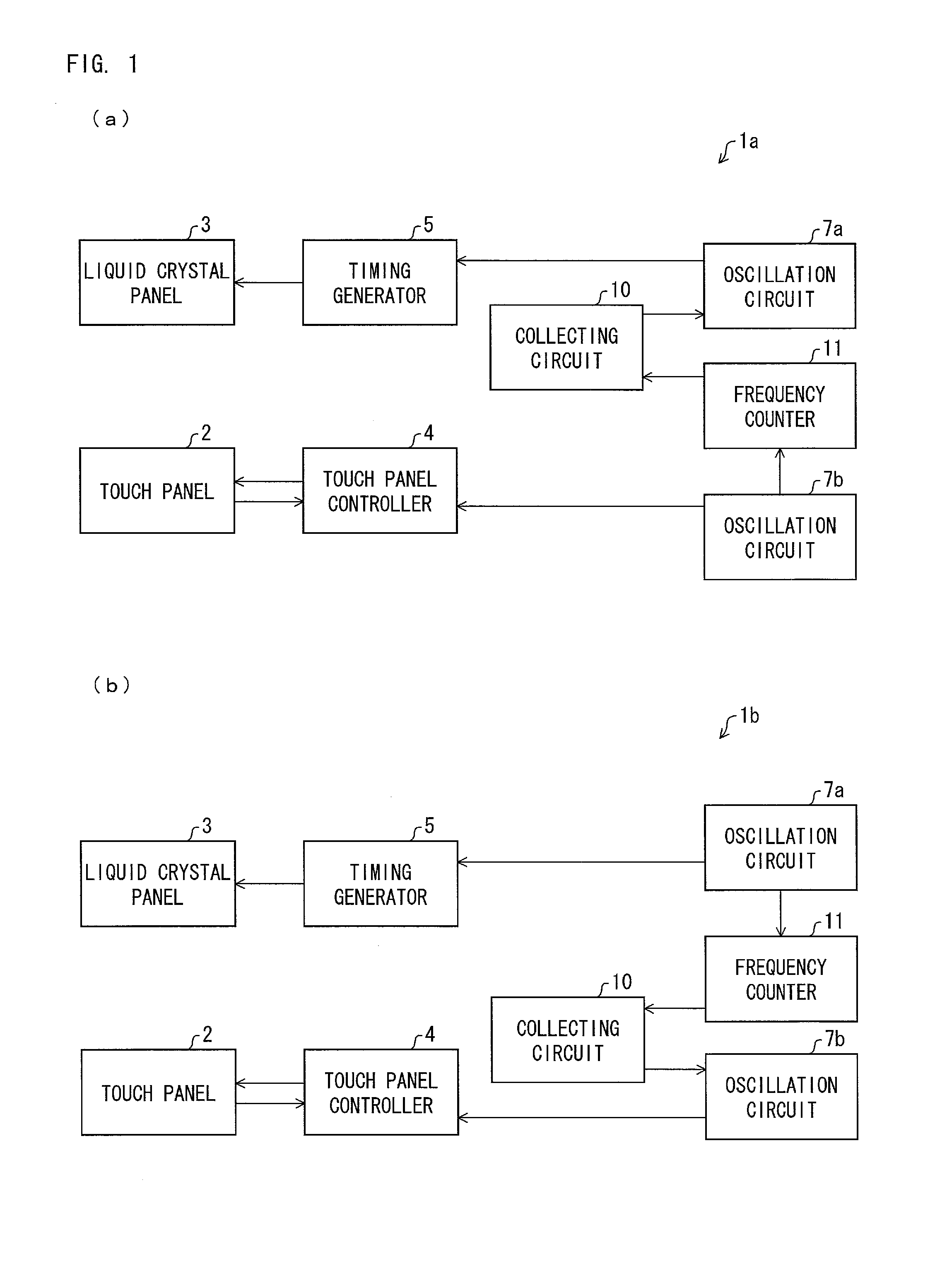
[0076]The above description has discussed a configuration in which the reference clock signal CLK of the oscillation circuit 7a is observed or corrected. Note, however, that the present invention is not necessarily limited to this. For example, advantageous effects of the present invention can be obtained also by observing or correcting signals (a horizontal synchronization signal Hsync, a vertical synchronization signal Vsync, a source start pulse SSPB, a gate start pulse GSPB, and the like) which are used in driving the liquid crystal panel 3. This is briefly described below.

[0077]As described above, instead of the reference clock signal CLK of the oscillation circuit 7a, synchronization signals such as the horizontal synchronization signal Hsync, the vertical synchronization signal Vsync, the source start pulse SSPB, the gate start pulse GSPB, and the like can be objects to be observed or corrected. For example, it is possible to employ a configuration in which the frequency coun...


PUM

PropertyMeasurementUnit
capacitanceaaaaaaaaaa

Abstract

A liquid crystal display devices (1a, 1b) each include a touch panel (2), a liquid crystal panel (3), a touch panel controller (4), a liquid crystal driving controller (timing generator) (5), oscillation circuits (7a, 7b), a correcting circuit (10), and a frequency counter (11). The frequency counter (11) counts a reference clock signal CLK supplied from the oscillation circuit (7a) or (7b). The correcting circuit (10) determines, in accordance with information supplied from the frequency counter (11), whether or not a frequency of the reference clock signal CLK is a predetermined frequency. In a case where the frequency of the reference clock signal CLK is not the predetermined frequency, the correcting circuit (10) corrects (i) a frequency at which the liquid crystal panel (3) is driven or (ii) a frequency at which sensing of the touch panel (2) is carried out.

Description

TECHNICAL FIELD[0001]The present invention relates to a liquid crystal display device equipped with a capacitive touch panel, and a method for driving the liquid crystal display device.BACKGROUND ART[0002]Recent years have witnessed a great increase of tablet electronic devices such as a portable phone, a personal computer and a music player, each of which is equipped with a touch panel. Such electronic devices display various operation buttons on their display screens. This allows a user to carry out an input operation to the electronic devices in a dialogue form by touching a desired operation button with the user's finger, or a pen or the like, instead of using a conventional user interface such as a keyboard or a button.[0003]A capacitive touch panel, which is a touch panel of a capacitive type that is one of operation types of touch panels, operates by detecting a change which is caused in a sensor by a capacitance of a human finger. One of main noises which occur during sensin...

Claims


Application Information

Patent Timeline
Patent Type & Authority Applications(United States)
IPC IPC(8): G02F1/1333
CPCG02F1/13338G06F3/0446G09G3/3648G09G2340/0435
Inventor FUJIOKA, AKIZUMIKUBOTA, AKINORI
Owner SHARP KK
Why Eureka
Try Eureka