Display case air duct partitioned for individual fans

a display case and air duct technology, applied in the field of refrigerated display cases, can solve the problems of uneven air curtain, inferior cooling of products contained within the display case, oscillation and fluctuation of air flow, etc., and achieve the effect of avoiding air buildup

Inactive Publication Date: 2005-12-13
HILL PHOENIX
View PDF8 Cites 5 Cited by
  • Summary
  • Abstract
  • Description
  • Claims
  • Application Information

AI Technical Summary

Benefits of technology

[0006]In contrast to existing refrigerated display cases, the inventive display case employs fans partitioned from each other so that air from one fan will not interfere with operation of the other fan. The partition may extend from the air inlet to the fans and downstream of the fans. Consequently, air is distributed more evenly through the cooling circuit, resulting in a uniform air curtain and efficient refrigeration.
[0010]In this way, each partition may form a wall with the fan panel. Thus, air within each chamber formed by each partition may avoid interfering with air in the other chamber. The refrigeration system avoids air build up over any one fan in an inexpensive manner.

Problems solved by technology

The build up of air over the fan results in the oscillation and fluctuation of air flow and an uneven air curtain across the viewing area as one side of the display case tends to receive more air than the other.
Such a design is undesirable, resulting in inferior cooling of product contained within the display case as well as inefficient refrigeration.

Method used


Image

  • Display case air duct partitioned for individual fans
  • Display case air duct partitioned for individual fans
  • Display case air duct partitioned for individual fans

Examples


Embodiment Construction

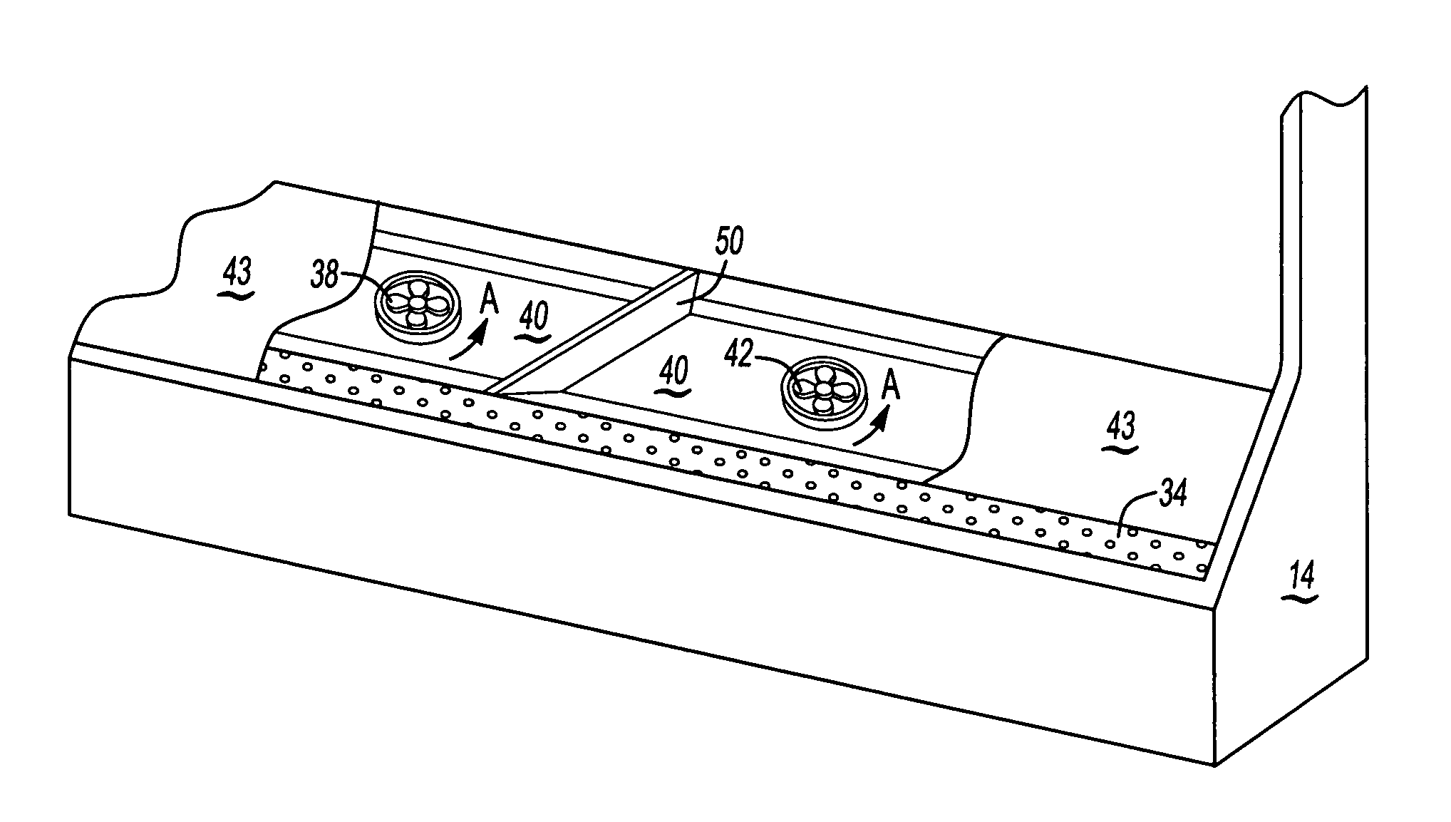
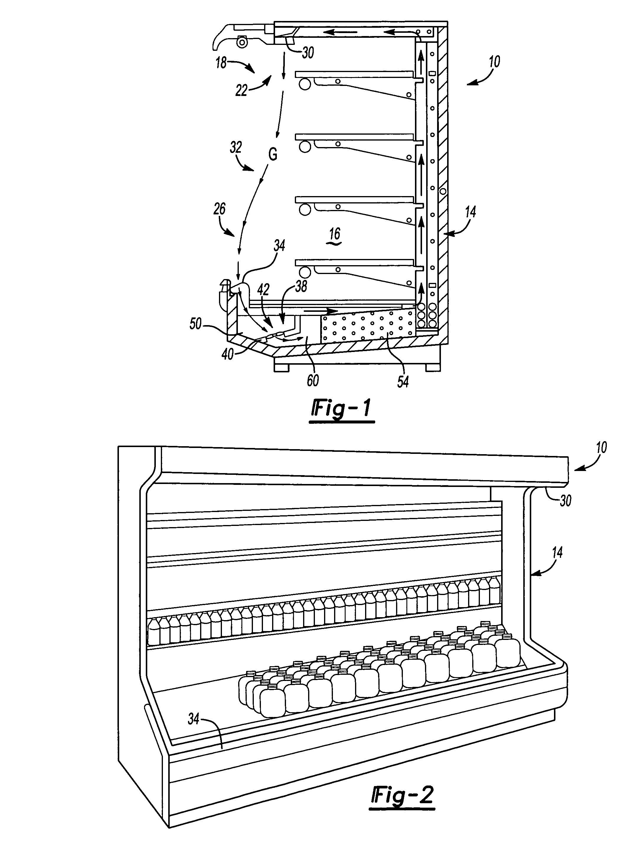
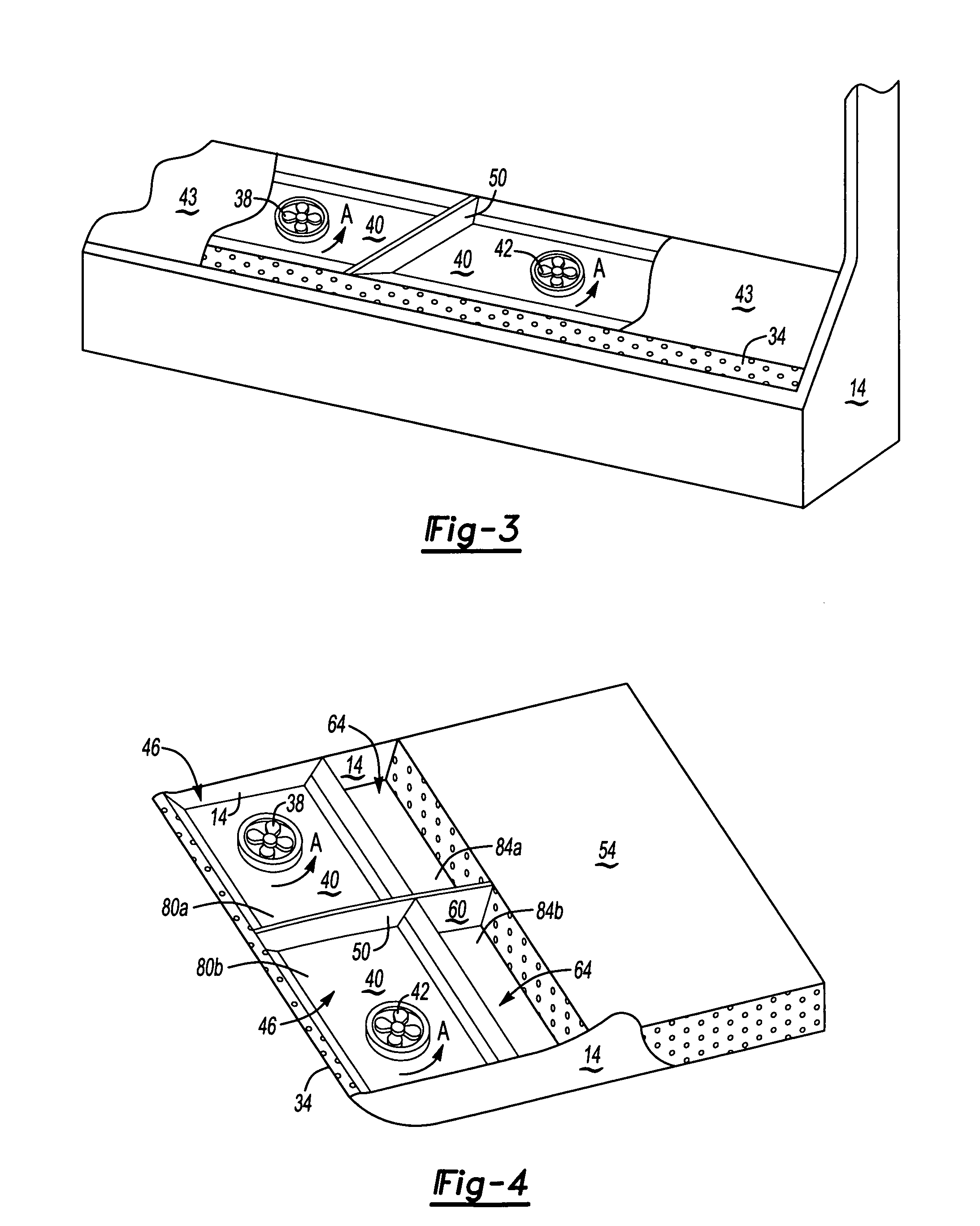
[0016]FIG. 1 illustrates a side view of refrigeration system 10, comprising display case 14 with first side 22, say a top, and second side 26, say a bottom. An area between first side 22 and second side 26 is open so as to create an open viewing area 18 that permits an individual to retrieve product contained within display case 14. To maintain a cool temperature within display case 14, air outlet 30 directs air along path G to air inlet 34, a warm air return, thereby forming air curtain 32. Air is returned to air inlet 34 and ultimately drawn by fans 38 and 42 over cooling element 54, such as a refrigeration coil, shown schematically, and then directed again to air outlet 30 as part of a cooling circuit cycle. As shown in FIG. 2, refrigeration system 10 has air outlet 30 extending over width of display case 14 to air inlet 34 found at the bottom of display case 14. These features of refrigeration system 10 are well known.

[0017]In contrast to these known features, refrigeration syst...


PUM


Abstract

A refrigeration system comprises a display case having a viewing area with the first side and a second side. An air outlet on the first side guides air across the viewing area to an air inlet on the second side. A first fan and a second fan communicate with the air inlet. A volume extends between the air inlet and the first and second fans. The partition divides this volume between the first and second fan.

Description

CROSS REFERENCE TO RELATED APPLICATIONS[0001]This application is a continuation of U.S. Nonprovisional patent application Ser. No. 10 / 265,018 filed on Oct. 4, 2002 now U.S. Pat. No 6,755,042.BACKGROUND OF THE INVENTION[0002]This invention relates to a refrigerated display case.[0003]Typically, a refrigerated display case includes a cold air discharge at one end of the case that blows cold air from the back of the case to the front of the case and over products contained therein. In addition, there is a diffuser at the top of the display case near the front that discharges cold air across the front opening of the display case. The diffuser includes a plurality of guide structures, known as straws, disposed to direct the flow of air perpendicular down the front opening of the display case. Cold air then flows to a warm air return at the bottom of the case, flowing back through a cooling circuit and out again through the cold air discharge.[0004]Fans generally move the air through the ...

Claims


Application Information

Patent Timeline
Patent Type & Authority Patents(United States)
IPC IPC(8): A47F3/04
CPCA47F3/0447
Inventor CHUANG, SUE-LI KINGSLEYDADDIS, JR., EUGENE DUANE
Owner HILL PHOENIX
Why Eureka
Try Eureka