Efficient air exhaust cooler

A cooler and high-efficiency technology, applied in the direction of exhaust devices, machines/engines, noise reduction devices, etc., can solve the problems of high power consumption and bulky cooling devices, and achieve the effect of low manufacturing cost, small size and high-efficiency cooling

Inactive Publication Date: 2011-06-15
靳北彪
View PDF5 Cites 6 Cited by
  • Summary
  • Abstract
  • Description
  • Claims
  • Application Information

AI Technical Summary

Problems solved by technology

However, traditional cooling devices have the disa

Method used


Image

  • Efficient air exhaust cooler
  • Efficient air exhaust cooler
  • Efficient air exhaust cooler

Examples


Embodiment 1

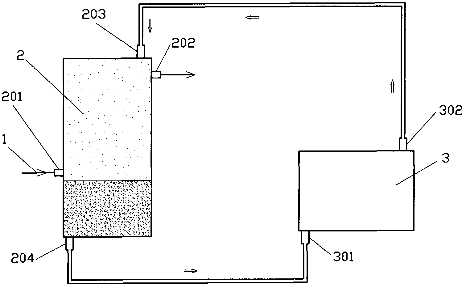
[0020] Such as figure 1 The exhaust gas high-efficiency cooler shown includes an engine exhaust passage 1, a mixer 2 and a heat exhauster 3, and an exhaust inlet 201, an exhaust outlet 202, a cooling liquid inlet 203 and a cooling liquid outlet 204 are arranged on the mixer 2 , the engine exhaust passage 1 communicates with the exhaust inlet 201 , the cooling liquid outlet 204 communicates with the cooled liquid inlet 301 of the heat exchanger 3 , and the cooled liquid outlet 302 of the heat exchanger 3 communicates with the cooling liquid inlet 203 .

Embodiment 2

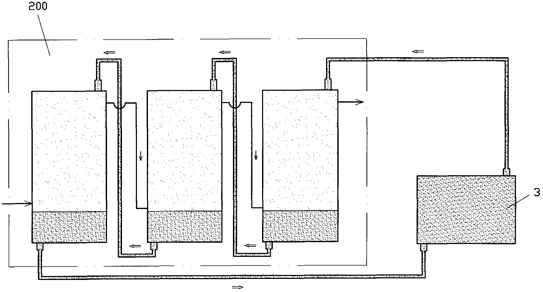
[0022] Such as figure 2 The difference between the exhaust gas high-efficiency cooler shown in Example 1 is that the mixer 2 is set as a multi-stage mixer 200 composed of two or more mixers 2 arranged in series in air flow and liquid flow in series.

Embodiment 3

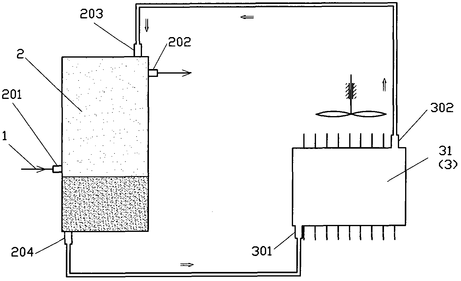
[0024] Such as image 3 The difference between the exhaust gas high-efficiency cooler shown in Embodiment 1 is that the radiator 3 is set as a radiator 31 .


PUM


Abstract

The invention discloses an efficient air exhaust cooler which comprises an engine air exhaust duct, a mixer and a heat radiator, wherein the mixer is provided with an air exhaust inlet, an air exhaust outlet, a cooling liquid inlet and a cooling liquid outlet; the engine air exhaust duct is communicated with the air exhaust inlet; the cooling liquid outlet is communicated with the cooled liquid inlet of the heat radiator; and the cooled liquid outlet of the heat radiator is communicated with the cooling liquid inlet. According to the invention, the exhaust air in a thermal motive system can be cooled, liquefied and/ or solidified efficiently.

Description

technical field [0001] The invention relates to the field of thermal energy and power, in particular to an exhaust high-efficiency cooler. Background technique [0002] With the improvement of human environmental awareness and in order to meet the requirements of special purposes, in thermal power systems (such as engines, gas turbines, etc.), there are many situations where it is necessary to cool, liquefy or solidify the exhaust gas, for example, to recover the carbon dioxide in the exhaust gas. The exhaust gas needs to be cooled, and the water vapor in it needs to be separated before sub-cooling to liquefy or solidify the carbon dioxide. In some cases, such as to effectively recirculate the exhaust gas from the combustion chamber, it is also necessary to cool the exhaust gas. But the traditional cooling device has the disadvantages of bulky size and high power consumption. Therefore, it is urgent to invent a new and efficient cooler to cool the exhaust gas. Contents o...

Claims


Application Information

Patent Timeline
IPC IPC(8): F01N3/04
Inventor 靳北彪
Owner 靳北彪
Why Eureka
Try Eureka