Optical instrument

a technology of optical instruments and optical instruments, applied in the field of optical instruments, can solve the problems of reducing the sensitivity of affecting the diagnosis of examiners, and inhibiting the receipt of light flux for eye refractive power measurement,

Inactive Publication Date: 2005-12-13
KK TOPCON
View PDF13 Cites 13 Cited by
  • Summary
  • Abstract
  • Description
  • Claims
  • Application Information

AI Technical Summary

Problems solved by technology

However, when the hole portion is made to a predetermined size or smaller, projection and receipt of a light flux for eye refractive power measurement are inhibited.
Thus, when a measurement area of a cornea shape measuring apparatus is increased, there is a possibility that a reduction in measurement sensitivity of eye refractive power is caused and an erroneous measurement result is calculated so that misdiagnosis of an examiner is induced.
As described above, there is a limitation with respect to the measurement area of the cornea shape so that the vicinity of the cornea central region cannot be measured.

Method used


Image

  • Optical instrument
  • Optical instrument
  • Optical instrument

Examples


Embodiment Construction

[0026]Hereinafter, an example of a preferred embodiment mode of the present invention will be specifically described with reference to the drawings.

[0027](Schematic Explanation)

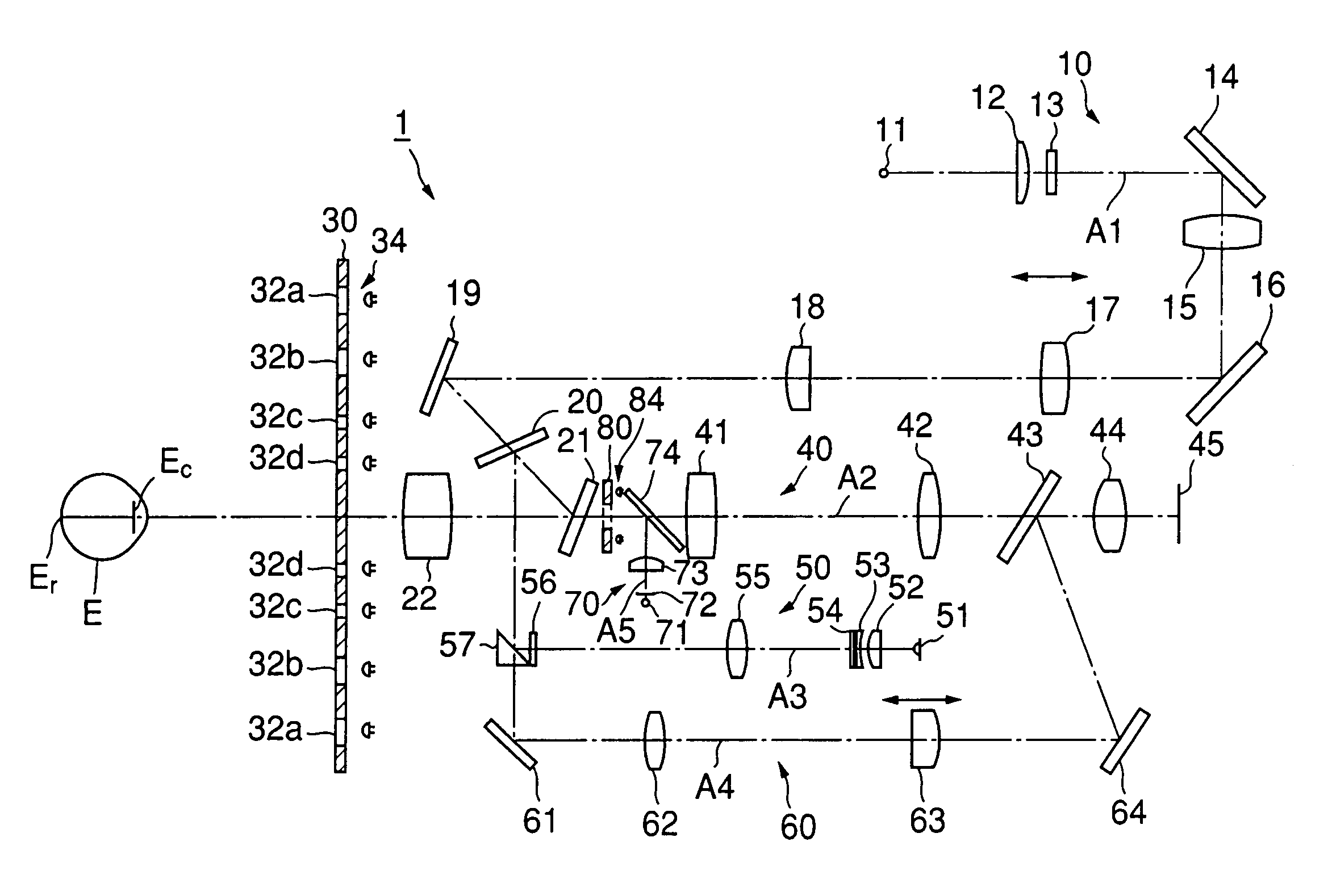
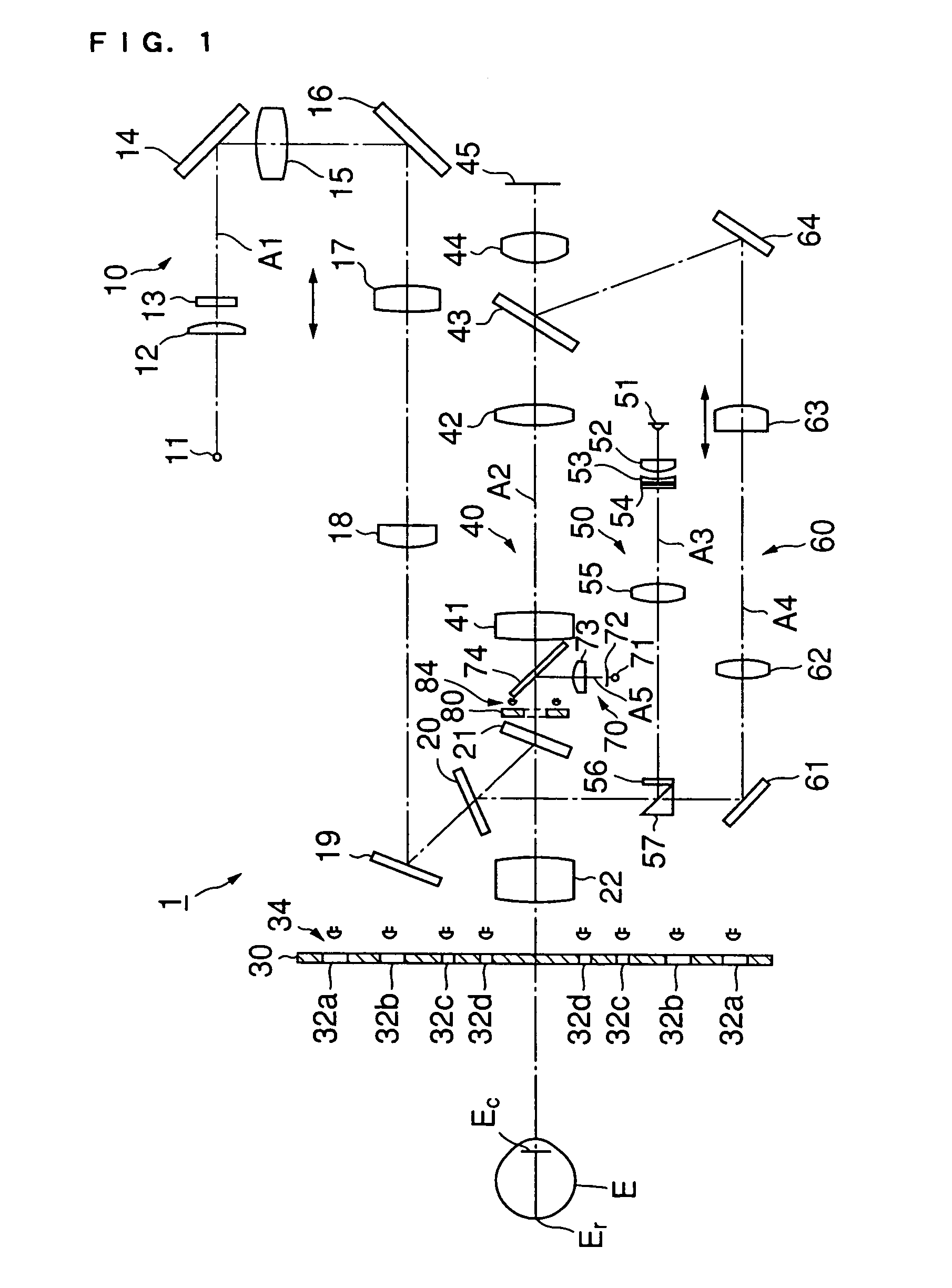
[0028]First, a schematic structure of an entire ophthalmologic apparatus of the present invention will be described with reference to FIG. 1. FIG. 1 is an explanatory view showing the ophthalmologic apparatus of this example.

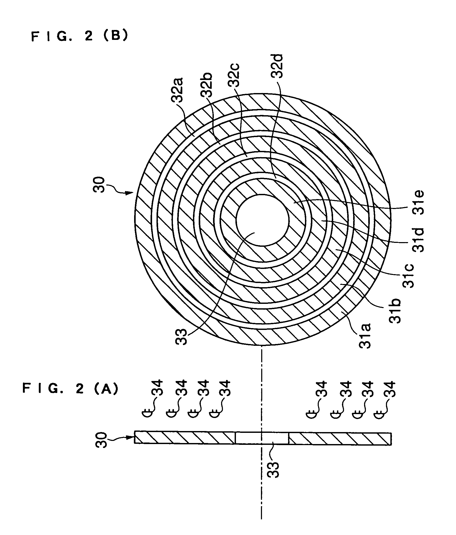
[0029]An ophthalmologic apparatus 1 of this example has a function for projecting a plurality of ring patterns to a cornea Ec of an eye to be examined E and measuring a shape of the cornea Ec based on a plurality of ring reflection images reflected on the eye to be examined E and a function for measuring eye refractive power of the eye to be examined E.

[0030]Specifically, as shown in FIG. 1, the ophthalmologic apparatus 1 is constructed to include a fixed index projecting optical system 10 for projecting a fixed index to the eye to be examined E to conduct fogging, a ring plate 30 for pro...


PUM


Abstract

An optical instrument comprising an eye refractive power measurement index optical system (50) for projecting an eye refractive power index in order to measure the refractive power of an eye (E) to be examined, a fixed index projecting optical system (10) for fixing / fogging the eye (E), an observation optical system (40) for observing the eye (E), a light receiving optical system (60), a ring plate (30) and an infrared LED (34) for projecting a cornea shape index used to measure the cornea shape of the eye (E), a ring plate (80) and an infrared LED (84) for projecting light to the center of the cornea via an objective lens (22), and an alignment index projecting optical system (70), whereby it is possible to project part of the cornea shape index onto the cornea (Ec) of the eye to be examined via the objective lens (22) of the observation optical system (40) for observation.

Description

CROSS-REFERENCES TO RELATED APPLICATIONS[0001]This application claims priority from Japanese Application No. 2000-241394, filed Aug. 9, 2000, and is a national-stage entry of International Application No. PCT / JP01 / 06813, filed Aug. 8, 2000.TECHNICAL FIELD[0002]The present invention relates to an ophthalmologic apparatus, and more particularly to an ophthalmologic apparatus for projecting an index to the cornea of an eye to be examined to conduct cornea measurement.BACKGROUND ART[0003]Conventionally, in order to measure a cornea shape with precision, a cornea shape measuring apparatus for projecting an index, for example, a Placido's pattern to the cornea of an eye to be examined has been known.[0004]Note that “cornea shape measurement” in this specification includes not only cornea mapping measurement for a central cornea shape of a cornea central region, a peripheral cornea shape of a cornea peripheral region, or the like but also measurement for, for example, a corneal curvature r...

Claims


Application Information

Patent Timeline
Patent Type & Authority Patents(United States)
IPC IPC(8): A61B3/10A61B3/103A61B3/107
CPCA61B3/103A61B3/107A61B3/10
Inventor HAYASHI, TAKEFUMI
Owner KK TOPCON
Why Eureka
Try Eureka