Power circuit for display driver, display device, and camera

a technology of power circuit and display device, which is applied in the direction of electric variable regulation, process and machine control, instruments, etc., can solve the problems of inaccurate integral multiples of the voltage ratio early battery service life, and inability to accurately calculate the integral multiple of the voltage between the lowest voltage and the highest voltag

Inactive Publication Date: 2005-12-13
CANON KK
View PDF7 Cites 11 Cited by
  • Summary
  • Abstract
  • Description
  • Claims
  • Application Information

AI Technical Summary

Benefits of technology

[0013]To solve the above problems, the present invention makes it possible to provide a display driver of display devices consuming a small current without requiring a complex circuit such as a charge pump circuit by using a series regulator of a very small current consumption constituted by a plurality of CMOS circuits or the like and thereby obtaining the voltages for multiplex driving mode from a voltage supplied from a power source such as a battery.
[0014]Moreover, when a voltage is equal to or lower than a power-source voltage, an output voltage of a series regulator is stable and it is possible to accurately raise a low voltage and a high voltage by integral multiples like in the case of a charge pump system even if the number of divided driving voltages increases.

Problems solved by technology

Therefore, a mobile unit for always displaying data by using a battery as a power source has a problem that the service life of the battery is early completed because it consumes a large power.
Therefore, when the number of divided voltages to be raised increases, a problem occurs that the voltage ratio between the lowest voltage and the highest voltage increases and higher-side voltages do not become accurate integral multiples due to a switching loss and the like.
Moreover, to supply stable power by using a charge-pump system, a circuit configuration becomes complex because it is necessary to stabilize power by using voltage stabilizer such as a series regulator and then boosting the power by a charge pump.
Furthermore, though some of liquid-crystal drivers respectively having a built-in a charge pump circuit are marketed, most liquid-crystal drivers do not have a charge pump in general.
Therefore, because charge-pump ICs for supplying LCD driver voltages are hardly marketed, it is actually difficult to constitute an LCD driver of a small current consumption by using a consumer IC.

Method used


Image

  • Power circuit for display driver, display device, and camera
  • Power circuit for display driver, display device, and camera
  • Power circuit for display driver, display device, and camera

Examples


second embodiment

(Second Embodiment)

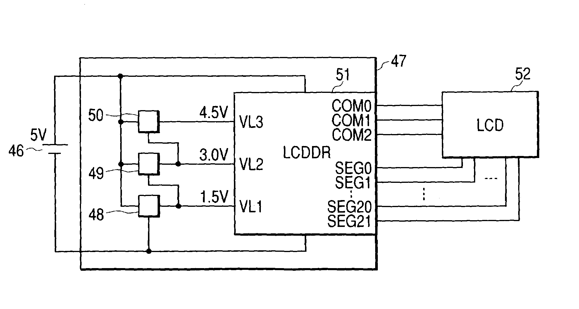
[0051]FIG. 5 is a block diagram showing a second configuration of the display driver of second embodiment of the present invention. In FIG. 5, symbol 36 denotes a battery serving as a power source and 37 denotes a regulator whose input is connected to the positive electrode of the battery 36 and whose VSS is connected to the negative electrode of the battery 36 to keep a voltage supplied from the battery 36 constant. In this case, the regulator outputs a voltage of 1.5 V. Symbol 38 denotes a regulator whose input is connected to the positive electrode of the battery 36 and whose VSS is connected to the negative electrode of the battery 36 to keep a voltage supplied from the battery 36 constant, which outputs 3.0 V which is a voltage two times higher than the output voltage of the regulator 37. Symbol 39 denotes a regulator whose input is connected to the positive electrode of the battery 36 and whose VSS is connected to the negative electrode of the battery 36 to ...


PUM

PropertyMeasurementUnit
voltageaaaaaaaaaa
voltageaaaaaaaaaa
voltageaaaaaaaaaa

Abstract

There is provided a power circuit for a display-device-driving circuit for supplying a plurality of voltages to a driving circuit for time-division-driving a display device, wherein each of the plurality of voltages are output via a constant-voltage circuit constituted by a regulator for dividing a voltage supplied from a power source and keeping divided voltages at a certain voltage level, whereby a stable power source consuming a small power to a driving circuit as a power source for a display device to be time-division-driven can be obtained.

Description

BACKGROUND OF THE INVENTION[0001]1. Field of the Invention[0002]The present invention relates to a power circuit for a display driver of a display device, particularly to a driving circuit of a liquid-crystal, device. More particularly, the present invention relates to a display device for performing to be multiplex driving, still more particularly relates to a power supplying circuit for driving a liquid-crystal device used for a liquid-crystal-driving circuit.[0003]2. Related Background Art[0004]FIGS. 8 and 9 show conventional liquid-crystal-driving-power supplying methods for multiplex driving a liquid-crystal device.[0005]FIG. 8 is an illustration showing the resistance-dividing type for driving a liquid crystal at a ⅓ bias. Symbol 101 denotes a battery serving as a power source, 102 denotes a regulator connected to the battery 101 for keeping a voltage supplied from the battery 101 constant, and 103, 104, and 105 denote resistances connected in series and having equal resistanc...

Claims


Application Information

Patent Timeline
Patent Type & Authority Patents(United States)
IPC IPC(8): G02F1/133G03B17/24G05F1/56G09G3/04G09G3/18G09G3/20G09G3/36
CPCG09G3/3696Y10S323/907
Inventor KASHIYAMA, RITSUO
Owner CANON KK
Why Eureka
Try Eureka