
Zoom lens system

Active Publication Date: 2005-12-13
ASAHI KOGAKU KOGYO KK
View PDF12 Cites 51 Cited by
  • Summary
  • Abstract
  • Description
  • Claims
  • Application Information

AI Technical Summary

Benefits of technology

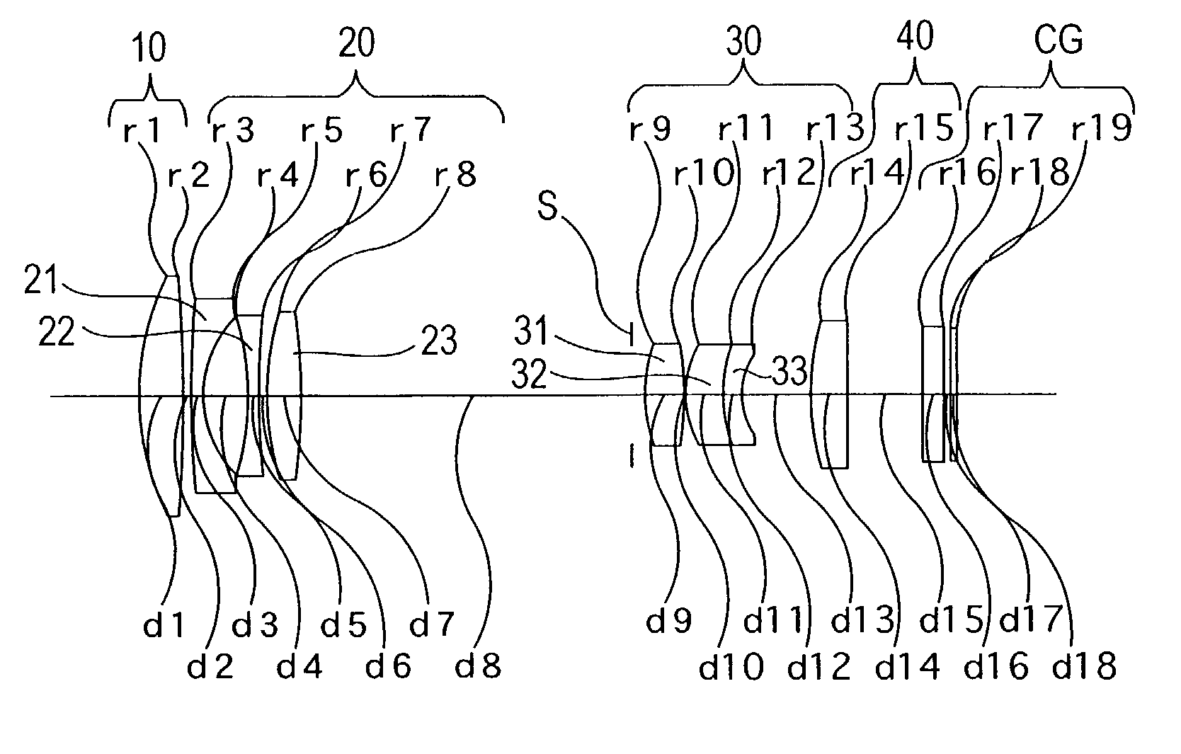
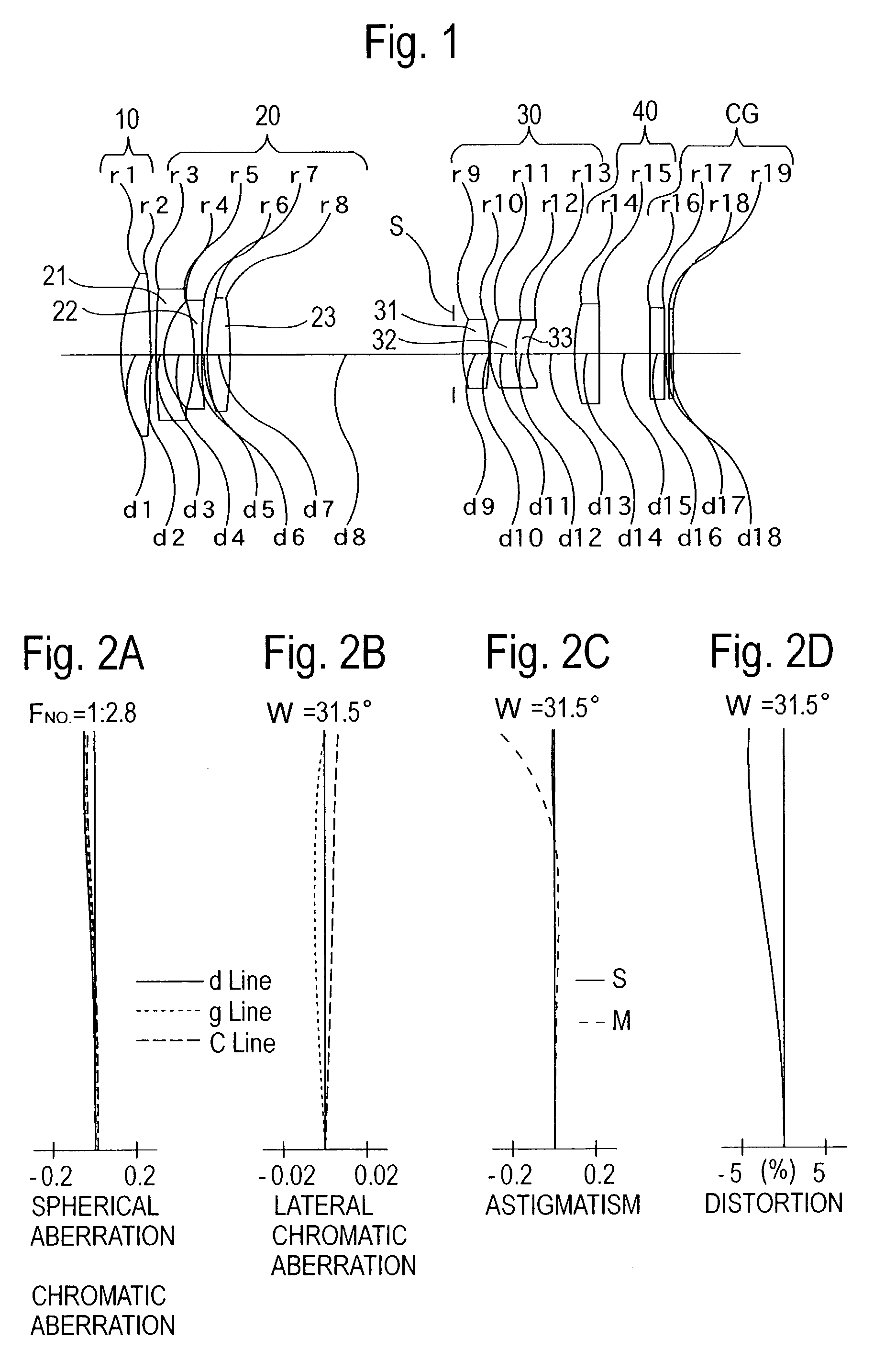
[0011]Upon zooming from the short focal length extremity to the long focal length extremity, the distance between the positive first lens group and the negative second lens group is increased; the distance between the negative second lens group and the positive third lens group is decreased; and the distance between the positive third lens group and the positive fourth lens group is increased.

Problems solved by technology

However, in such a zoom lens system, it is difficult to achieve a zoom ratio of more than 4.
In this zoom lens system, a zoom ratio of about 6 is achieved; however, the lens diameter of the front lens group is large, and miniaturization thereof is insufficient.
As another example, a zoom lens system disclosed in U.S. Pat. No. 5,570,233 achieves a wide angle-of-view, i.e., a sufficient short focal length at the short focal length extremity; however, the diameter of the front lens group is large, and a large number of lens elements are required.
Accordingly, this zoom lens system is not appropriate for a camera having a telescoping zoom lens system.
Generally, if an attempt is made to reduce the number of lens elements in order to reduce the thickness of the lens groups, the correcting of aberrations, on the other hand, becomes difficult.

Method used


Image

  • Zoom lens system
  • Zoom lens system
  • Zoom lens system

Examples


embodiment 2

[Embodiment 2]

[0075]FIG. 5 is the lens arrangement of the zoom lens system according to the second embodiment of the present invention. FIGS. 6A through 6D show aberrations occurred in the lens arrangement shown in FIG. 5 at the short focal length extremity. FIGS. 7A through 7D show aberrations occurred in the lens arrangement shown in FIG. 5 at an intermediate focal length. FIGS. 8A through 8D show aberrations occurred in the lens arrangement shown in FIG. 5 at the long focal length extremity. Table 2 shows the numerical data of the second embodiment.

[0076]The basic lens arrangement is the same as that of the first embodiment except that for the positive third lens group 30 includes a positive lens element 31 and a negative lens element 32, in this order from the object. The diaphragm S is provided 0.97 mm in front (on the object side) of the positive third lens group 30 (surface No. 9).

[0077]

TABLE 2FNO = 1:2.8–3.5–4.7f = 8.00–18.00–38.00W = 31.4–14.2–7.0fB = 0.00—0.00—0.00Surf. No...

embodiment 3

[Embodiment 3]

[0080]FIG. 9 is the lens arrangement of the zoom lens system according to the third embodiment of the present invention. FIGS. 10A through 10D show aberrations occurred in the lens arrangement shown in FIG. 9 at the short focal length extremity. FIGS. 11A through 11D show aberrations occurred in the lens arrangement shown in FIG. 9 at an intermediate focal length. FIGS. 12A through 2D show aberrations occurred in the lens arrangement shown in FIG. 9 at the long focal length extremity. Table 3 shows the numerical data of the third embodiment.

[0081]The basic lens arrangement is the same as that of the first embodiment except that (i) the positive first lens group 10 includes cemented lens elements having a negative lens element 11 and a positive lens element 12; and (ii) the positive third lens group 30 includes a positive lens element 31, cemented lens elements having a positive lens element 32 and a negative lens element 33, and a negative lens element 34, in this orde...

embodiment 4

[Embodiment 4]

[0085]FIG. 13 is the lens arrangement of the zoom lens system according to the fourth embodiment of the present invention. FIGS. 14A through 14D show aberrations occurred in the lens arrangement shown in FIG. 13 at the short focal length extremity. FIGS. 15A through 15D show aberrations occurred in the lens arrangement shown in FIG. 13 at an intermediate focal length. FIGS. 16A through 16D show aberrations occurred in the lens arrangement shown in FIG. 13 at the long focal length extremity. Table 4 shows the numerical data of the fourth embodiment.

[0086]The basic lens arrangement is the same as that of the first embodiment except that (i) the positive first lens group 10 includes cemented lens elements having a negative lens element 11 and a positive lens element 12; and (ii) the positive third lens group 30 includes a positive lens element 31, a positive lens element 32, and a negative lens element 33, in this order from the object (without including a cemented lens e...


PUM


Abstract

A zoom lens system includes a movable positive first lens group, a movable negative second lens group, a movable positive third lens group, and movable stationary or positive fourth lens group. Upon zooming, the distance between the first and second lens groups is increased; the distance between the second and the third lens groups is decreased; and the distance between the third and the fourth lens groups is increased.

Description

BACKGROUND OF THE INVENTION[0001]1. Field of the Invention[0002]The present invention relates to a zoom lens system mainly used in an electronic still camera (digital camera) having a zoom ratio more than 4 and including a wide angle range (half angle-of-view of more than 30°).[0003]2. Description of the Prior Art[0004]In recent years, there has been an increasing need for further miniaturization and higher definition in digital cameras; and the pixels of CCD imaging devices are further miniaturized. Accordingly, photographic lens systems of such digital cameras are required to have high resolution. Furthermore, a long back focal distance is also required in order to accommodate a filter group. In addition, an optical system for a color CCD is required to have good ‘telecentricity’ in order to prevent shading and color shift, i.e., the light rays which exit from the final lens surface and are incident on the imaging surface are to be as perpendicular to the imaging surface as possib...

Claims


Application Information

Patent Timeline
IPC IPC(8): G02B15/20G02B13/18G02B15/173
CPCG02B15/173G02B15/144113
Inventor EGUCHI, MASARU
Owner ASAHI KOGAKU KOGYO KK
Features
  • Generate Ideas
  • Intellectual Property
  • Life Sciences
  • Materials
  • Tech Scout
  • Unparalleled Data Quality
  • Higher Quality Content
  • 60% Fewer Hallucinations
Learn More