Network monitoring system with built-in monitoring data gathering

a monitoring system and monitoring system technology, applied in the field of network monitoring systems with built-in monitoring data gathering, can solve problems such as limiting its performance, packet loss, internal queues delaying data through the router,

Inactive Publication Date: 2005-12-13
AGILENT TECH INC
View PDF7 Cites 115 Cited by
  • Summary
  • Abstract
  • Description
  • Claims
  • Application Information

AI Technical Summary

Problems solved by technology

The router architecture just described has a number of aspects that can limit its performance.
For example, the internal queues can delay data through the router if the data routes connected to the router are busy.
Moreover, packets can be lost if the quantity of data received for transmission to a given destination exceeds the quantity of data that can be transmitted to this destination.
However, lost or delayed packets can be an issue for certain services, such as when the network is used to transmit packets of audio and video data, or when the network owner has entered into a service level agreement in which a given quality of service is guaranteed to a user.
Conventionally, when large quantities of data are distributed among multiple routes, the routing pattern is fixed in advance and therefore cannot take into account the traffic sharing each route.
Some routers include rudimentary systems for collecting monitoring data, but the monitoring data generated by such data collection systems have such a high granularity that bursty traffic is significantly under-recorded.
It is bursty traffic that most seriously taxes the transmission capabilities of a network.
However, such test devices are inconvenient to use because the interruption of the connections between the channel cards of the router and the network or user.
Moreover, such text devices are expensive since they duplicate a substantial portion of the circuitry of the router.
It would be expensive to use such test devices to monitor the performance of the number of routers that would be required to provide an accurate picture of the network performance and to provide the above additional features.

Method used


Image

  • Network monitoring system with built-in monitoring data gathering
  • Network monitoring system with built-in monitoring data gathering
  • Network monitoring system with built-in monitoring data gathering

Examples


first embodiment

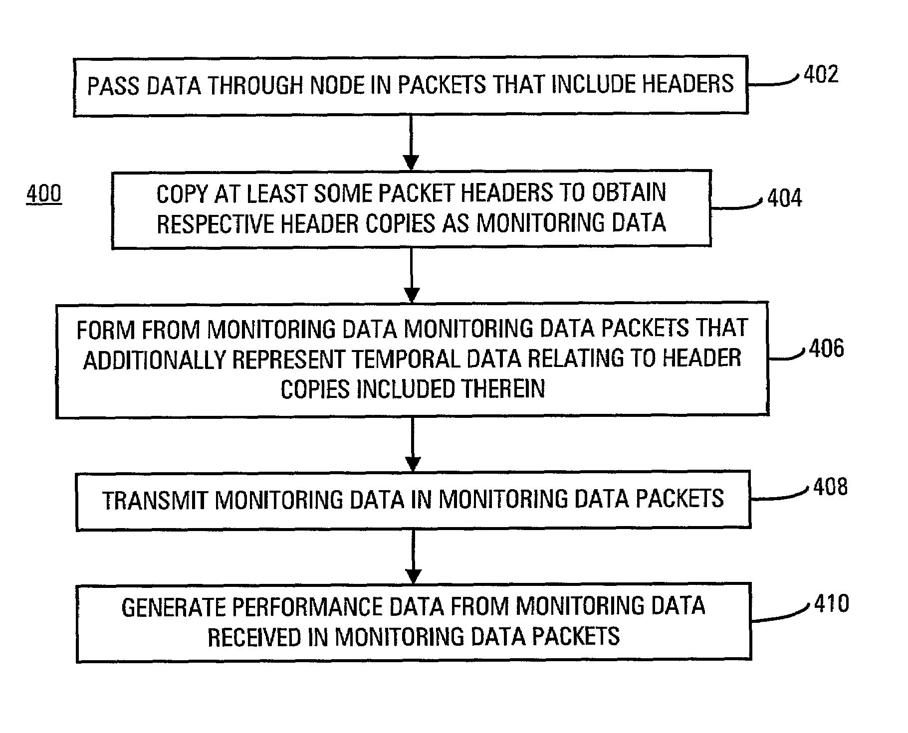
[0144]FIG. 8B illustrates the performance data generating process 410.

[0145]In process 420, a data base is built of the monitoring data received in the monitoring data packets.

[0146]In process 422, the monitoring data in the data base are analyzed to generate the performance data.

[0147]The performance data may relate to the performance of the node where the performance data are gathered.

[0148]Either or both of the monitoring data and the performance data derived at least in part from the monitoring data may be transmitted to one or more other nodes of the network as additional data. This enables performance data relating to the performance of the network to be generated. Performance data relating to the performance of the network may be generated by performing hierarchical processing of monitoring data and performance data received from nodes of the network.

second embodiment

[0149]FIG. 8C illustrates the performance generating process 410.

[0150]In process 430, additional data relating to at least one additional node of the network are received. The additional data include either or both monitoring data and performance data.

[0151]In process 432, the monitoring data and the additional data are analyzed to generate the performance data. The performance data generated relate to the performance of the network.

[0152]FIG. 8D illustrates an alternative embodiment of process 432 shown in FIG. 8C.

[0153]In process 440, ones of the monitoring data and the additional data including headers having identical source and destination addresses are identified.

[0154]In process 442, the performance data are determined from the identified ones of the monitoring data and additional data. The performance data generated relate to the performance of a connection through the network between the source and destination.

[0155]The method 400 may additionally include controlling the n...


PUM


Abstract

The network monitoring system comprises a network router with built-in monitoring data gathering. The network router includes channels through which data pass in packets. Each of the packets includes a packet header. The network router additionally includes a header copier and a packet generator. The header copier generates a header copy from the packet header of at least some of the packets. The packet generator receives the header copies and forms monitoring data packets from them. Each monitoring data packet additionally represents temporal data relating to the header copies included in it. A method of obtaining performance data relating to a data transmission network that includes a node passes data through the node in packets. Each of the packets includes a packet header. At least some of the packet headers are copied to obtain respective header copies as monitoring data from which monitoring data packets are formed. The monitoring data packets additionally represent temporal data relating to the header copies included in them. The monitoring data packets are transmitted and the performance data are generated from the monitoring data contained in the monitoring data packets.

Description

[0001]This application claims benefit of provisional application 60 / 201,614, filed May 3, 2000.BACKGROUND OF THE INVENTION[0002]Network routers control the flow of data traffic in networks, between networks and between networks and end users. Basic information on routers and their use in networks is disclosed by Radia Perlman in the book entitled INTERCONNECTIONS, the second edition of which was published by Addison-Wesley in 1999.[0003]FIG. 1A shows the structure of a typical router 10. The router is composed of a number of channel cards 12 connected to the backplane 14. The channel cards receive packets of data from and transmit packets of data to the user or the network. The channel cards additionally receive packets of data from and transmit packets of data to the backplane. The packets of data transmitted to or from the backplane differ from those transmitted to and from the network or user and will be called envelopes to distinguish them.[0004]The backplane 14 transmits envelo...

Claims


Application Information

Patent Timeline
Patent Type & Authority Patents(United States)
IPC IPC(8): H04L12/24H04L12/26
CPCH04L43/026H04L41/5003H04L41/5029H04L41/509H04L43/0829H04L43/0852H04L43/0888H04L43/106
Inventor WALKER, RICHARD C.AMRUTUR, BHARADWAJMOTTISHAW, PETERJOINER, C. STEVENCHESLER, LARRY A.HARDCASTLE, IAN
Owner AGILENT TECH INC
Why Eureka
Try Eureka