Card connector with two-stage ejection mechanism and card-retaining mechanism

a card connector and two-stage technology, applied in the direction of coupling device connection, instruments, conveying record carriers, etc., can solve the problems of difficult to satisfy the need to make a card connector compact and light weight, memory card to be drawn out, and difficult to retain therein, etc., to achieve stable retention, reliably retained, and stable

Inactive Publication Date: 2005-12-20
CHENG UEI PRECISION IND CO LTD
View PDF6 Cites 22 Cited by
  • Summary
  • Abstract
  • Description
  • Claims
  • Application Information

AI Technical Summary

Benefits of technology

[0018]As the above description, the support elastic slice would become ineffective due to fatigue by means of the connection between the guiding arm of the support elastic slice and the guiding groove of the shielding case cover and the connection between the retaining portion of the support elastic slice and the groove of the memory card. The support elastic slice is also impossible to release the engagement with the slider. Furthermore, when the memory card is located at the retaining position, the guiding arm closely props the outside side border of the guiding groove to make the retaining portion unable to move horizontally and release the engagement with the memory card due to the elasticity of the supporting elastic slice, so that the memory card can be stably and reliably retained in the card connector. The slide, the supporting elastic slice and the pressing elastic slice are formed as a whole, so that the card connector is compact and light-weight and has enough room to accommodate the supporting pin that passes through the spring. In addition, when the memory card is inserted into the card inserting space, the side border of the memory card would not deform due to the friction with the supporting part because the support elastic slice is inclined in the opposite card-inserting direction. Accordingly, the memory card is stably and reliably retained in the card connector. The card connector would become more compact and more light-weight due to the height decrease to the concave slice of the slider.

Problems solved by technology

It is difficult to satisfy the need to make a card connector compact and light-weight.
Furthermore, only depending on the elasticity of the pin support to engage a notch of the memory card with the J-shaped engaging projection for retaining would cause the memory card to be drawn out from the card connector easily, but to be retained therein difficultly.
When the memory card is repeatedly inserted and extracted by means of the persistent propping of the guiding portion, although the memory card can be reliably retained in the card connector, the stress on the back of the retaining elastic pin connected with the slider is intensive.
Additionally, the retaining elastic pin is easy to be distorted due to fatigue, even to release the engagement with the slider, because the retaining elastic pin is separately formed with the slider as a whole.
In addition, the pressing elastic pin used to confine the pin member is not designed as a whole.
It is difficult to make the card connector compact and light-weight.
A pressing portion is extended from the front of the plastic slider, so that it cannot make the card connector compact and light-weight enough due to too large volume.
Furthermore, because the engagement between the pressing portion and the pin member is inelastic, it is easy for the pressing portion to release the engagement for the pin member and become ineffective due to fatigue.
Accordingly, the retaining elastic pin releases the engagement with the groove of the memory card to make the memory card difficult to be reliably retained.
Furthermore, it is possible for the retaining elastic pin to release the engagement with the slider and difficult to make the card connector compact and light-weight.

Method used


Image

  • Card connector with two-stage ejection mechanism and card-retaining mechanism
  • Card connector with two-stage ejection mechanism and card-retaining mechanism
  • Card connector with two-stage ejection mechanism and card-retaining mechanism

Examples


Embodiment Construction

[0023]Now, embodiments of the present invention will be described in detail by referring to the accompanying drawings.

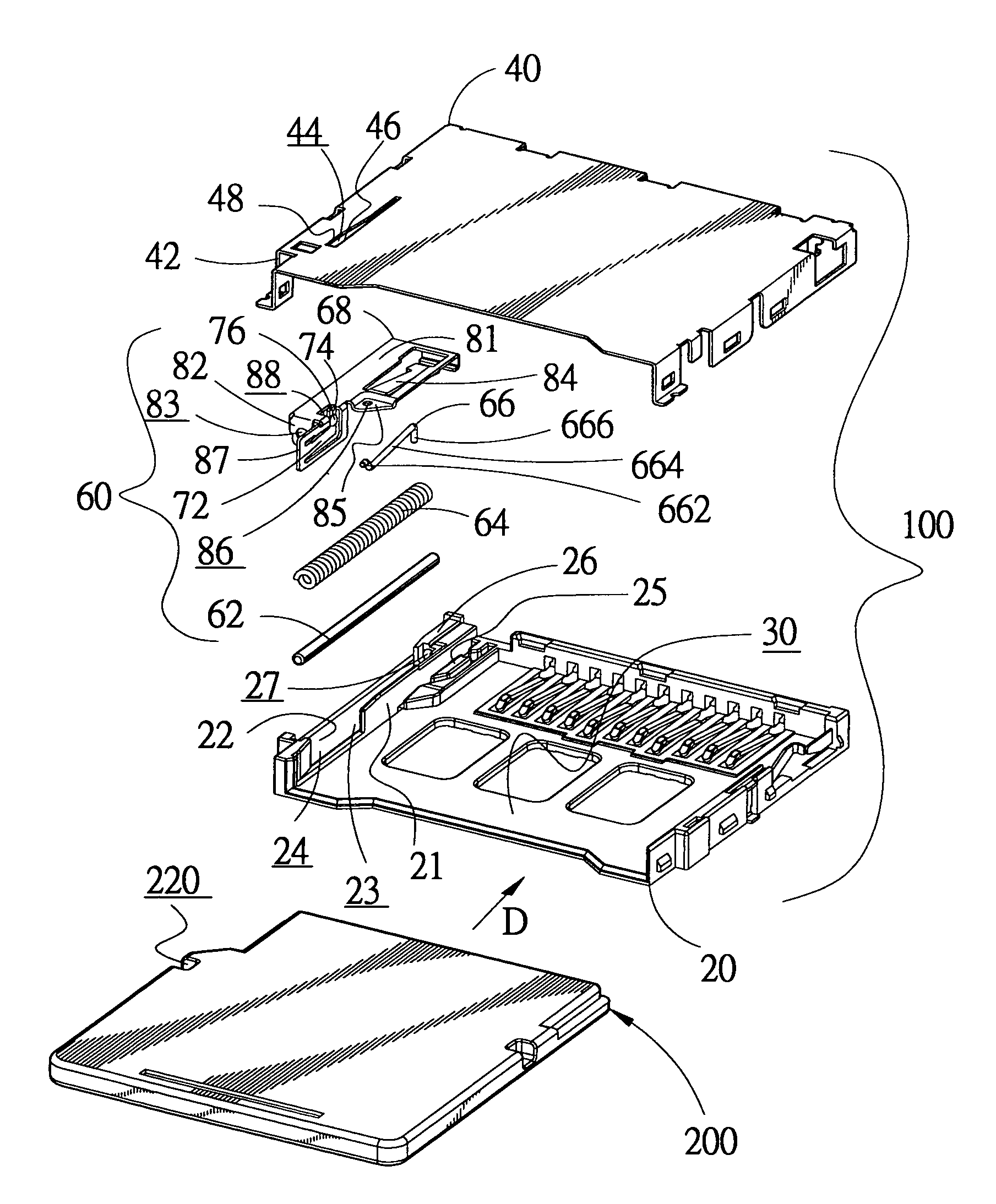
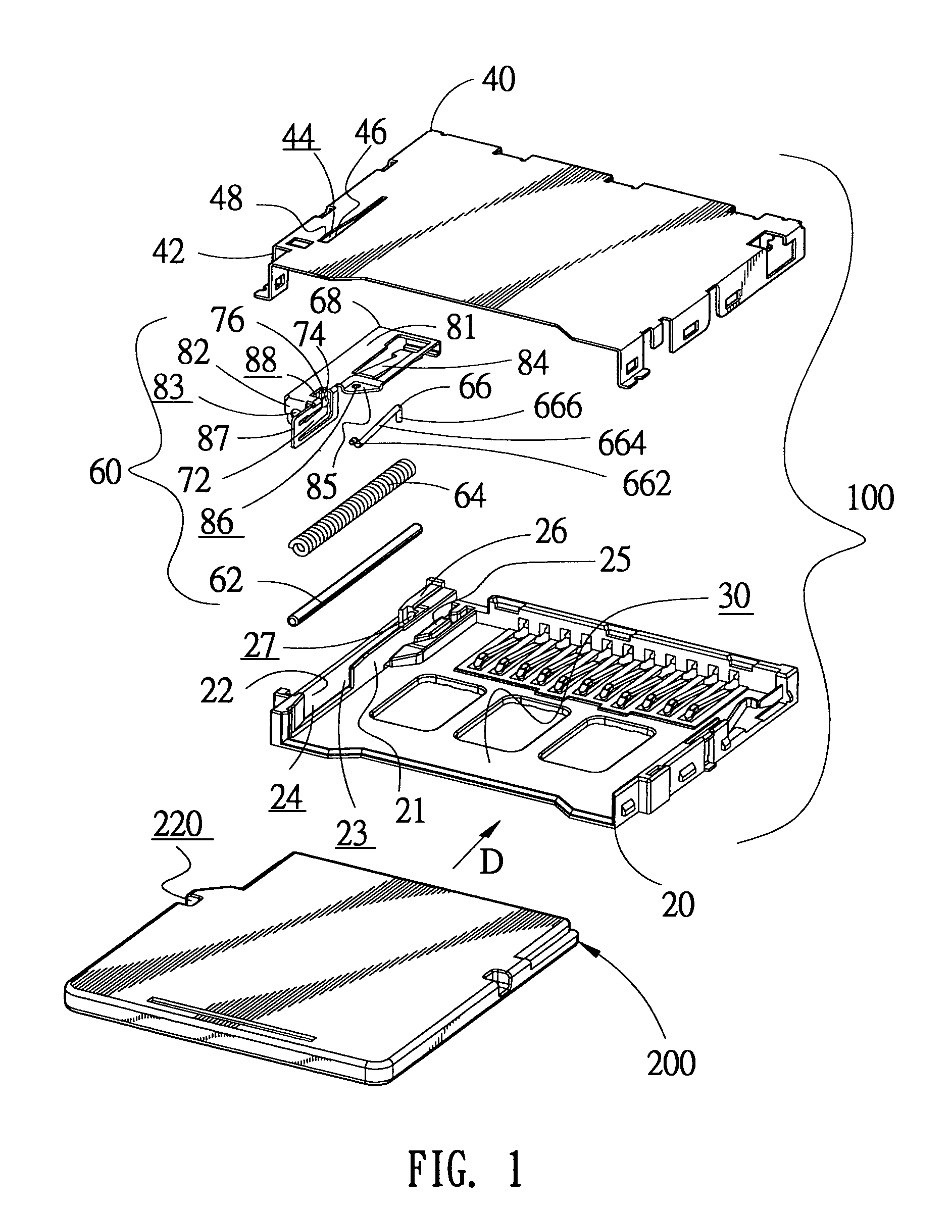
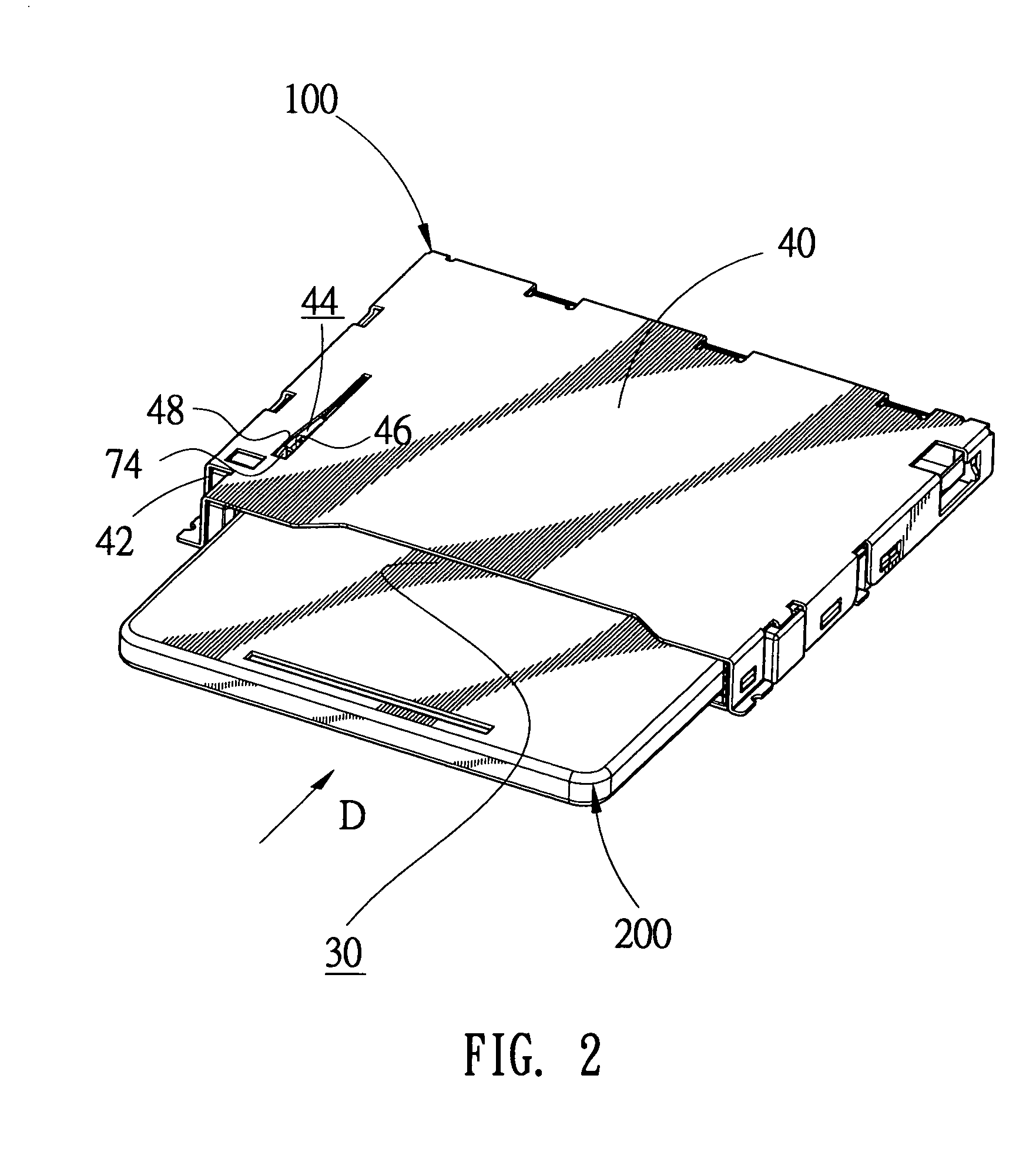
[0024]As FIG. 1 illustrated, the present invention provides a card connector that has a two-stage ejection mechanism and a card-retaining mechanism. The card connector 100 comprises a plastic case body 20, a shielding case cover 40 and a two-stage ejection mechanism 60 assembled between the plastic case body 20 and the shielding case cover 40. A card inserting space 30 is formed between the plastic case body 20 and the shielding case cover 40. The plastic case body 20 and the shielding case cover 40 are engaged with each other to form the card inserting space 30. A memory card 200 inserts the card inserting space 30 from the front of the card inserting space 30 in the direction-D and stays therein.

[0025]A housing space 23 is formed between a partitioning wall 21 extended from one side of the plastic case body 20 and a side wall 22 of the plastic case body 20. There i...


PUM


Abstract

The present invention provides a card connector with two-stage ejection mechanism and card-retaining mechanism. The card connector includes a plastic case body, a shielding case cover and a two-stage ejection mechanism assembled therebetween. The plastic case body has a heart-shaped cam groove for engagement with a pin member. The shielding case cover has a guiding groove. A flexural border is formed on one side of the side border of the guiding groove. The two-stage ejection mechanism includes a slider. The retaining elastic pin extends a retaining portion towards the memory card for engagement with a groove on one side of the memory card, so that the memory is stably and reliably retained and the card connector is compact and light-weight.

Description

BACKGROUND OF THE INVENTION[0001]1. Field of the Invention[0002]The present invention relates generally to a card connector, and more specifically to a card connector with two-stage ejection mechanism and card-retaining mechanism, a memory card can be stably and reliably retained in the card connector.[0003]2. The Related Art[0004]Nowadays, with the development of Personal Computer and the related electronic products, many kinds of memory cards are widely applied, such as PCMCIA (Personal Computer Memory Card International Association) card, SD (Secure Digital) card and CF (Compact Flash) card. Accordingly, card connectors applied in such products appear. Especially, the card connector with two-stage ejection mechanism and card-retaining mechanism is widely applied.[0005]U.S. Pat. No. 6,537,090 discloses a card connector with two-stage ejection mechanism and card-retaining mechanism. The card connector comprises a case cover, a plastic case for engagement with the case cover, a card...

Claims


Application Information

Patent Timeline
Patent Type & Authority Patents(United States)
IPC IPC(8): G06K13/08H01R13/24H01R13/62H01R13/635
CPCG06K13/08G06K13/0806G06K13/0825H01R13/635H01R13/24
Inventor SU, CHIA SHENG
Owner CHENG UEI PRECISION IND CO LTD
Why Eureka
Try Eureka