Network connection sensing assembly

Inactive Publication Date: 2005-12-20
TE CONNECTIVITY CORP
View PDF7 Cites 174 Cited by
  • Summary
  • Abstract
  • Description
  • Claims
  • Application Information

AI Technical Summary

Problems solved by technology

For example, if one network component is connected to the wrong server, a network shutdown or outage may occur which could be very costly.
However, the conventional interconnect module 600 suffers from several drawbacks.
The process of installing the FEC 602 is thus time consuming and difficult, especially when the interconnect module 600 is located in a space-constrained network structure.
The second connector hangs from the front side of the interconnect module 600 and is thus easily damaged during installation and use.
Also, the second connector takes up a great deal of space which renders the interconn

Method used


Image

  • Network connection sensing assembly
  • Network connection sensing assembly
  • Network connection sensing assembly

Examples


Embodiment Construction

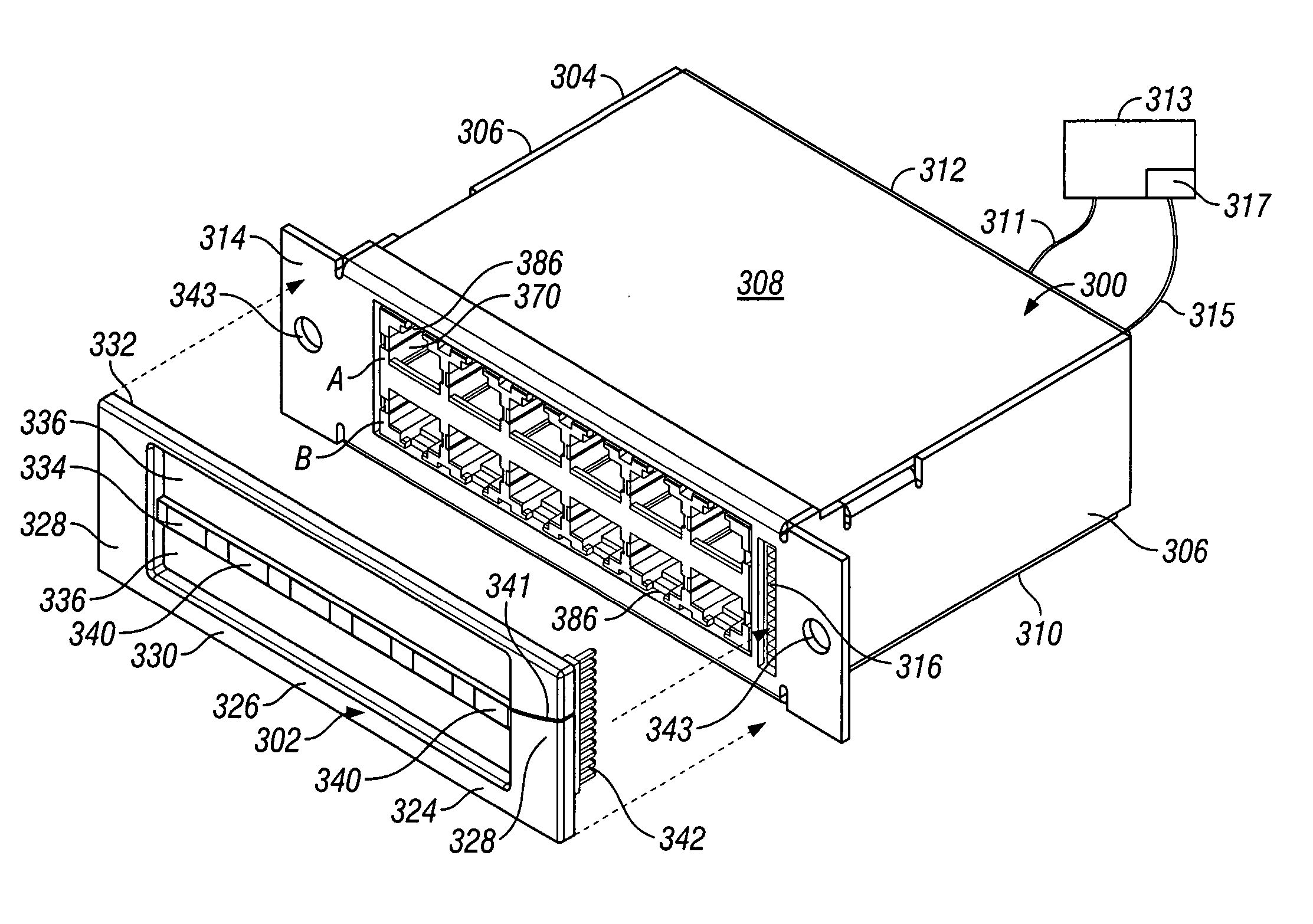
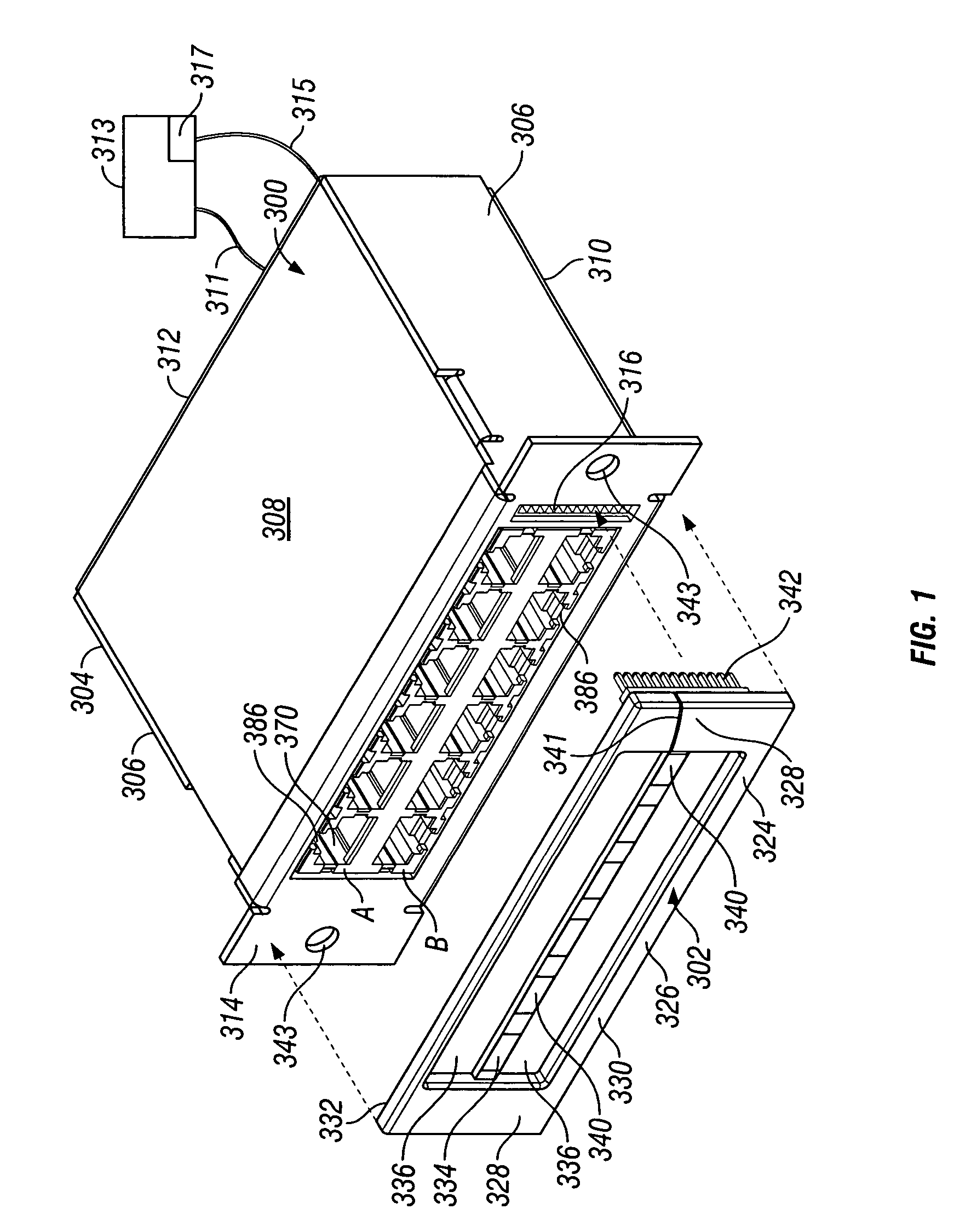
[0022]FIG. 1 illustrates a front isometric view of an interconnect cassette 300 configured to be mated with a separate and discrete sensor strip assembly 350 according to an embodiment of the present invention. The interconnect cassette 300 includes a housing 304 defined by side walls 306, a top surface 308, a base 310, a rear wall 312 and a jack interface 314. The jack interface 314 includes a plurality of receptacle jacks 370 and sensor strip pin receptacles 316 positioned to the side of the receptacle jacks 370. The receptacle jacks 370 each have a channel 386 along one side thereof and are configured to receive plugs 18 (as shown in FIG. 2) on patch cords 10.

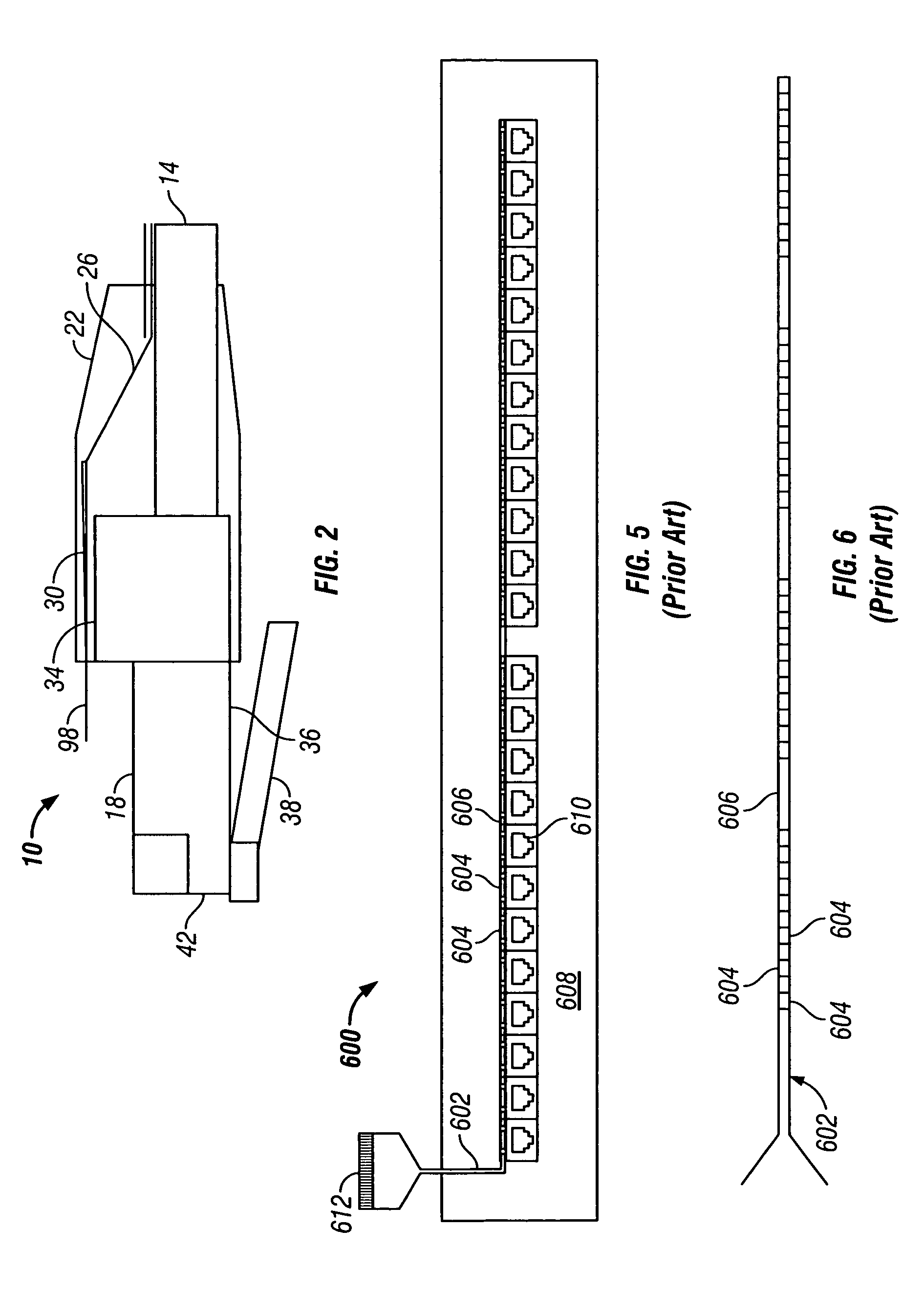
[0023]FIG. 2 illustrates a side sectional view of a portion of a patch cord 10 formed according to an embodiment of the present invention. The patch cord 10 includes an insulated cable 14 and a plug 18 retained in a boot 22. The cable 14 extends to a first network component (not shown) that, by way of example only, may be a ...


PUM


Abstract

A connector assembly includes a housing having a jack interface. The jack interface has a receptacle jack therein, and the receptacle jack is configured to receive a plug. A sensor bezel is removably attachable to the jack interface, and the sensor bezel comprises a cavity extending therethrough to allow passage of a plug when inserted into the receptacle jack. The sensor bezel includes a circuit board proximate the jack cavity. At least one sensor contact is aligned with, and configured to engage, a sensor probe associated with a plug insertable into the receptacle jack. An interchangeable output cassette provides an output signal through the front or the rear of the connector assembly.

Description

CROSS REFERENCE TO RELATED APPLICATIONS[0001]This application claims the benefit of U.S. Provisional Application Ser. No. 60 / 453,801 filed Mar. 11, 2003, which is hereby incorporated by reference in its entirety, and this application is a continuation-in-part application of U.S. patent application Ser. No. 10 / 289,570 filed Nov. 7, 2002, which is also hereby incorporated by reference in its entirety.BACKGROUND OF THE INVENTION[0002]The present invention generally relates to a connector that connects electronic components in a network and, more particularly, relates to an interconnect module or cassette that connects network components to a sensor component.[0003]In order to better operate large electronic networks, sensor systems have been developed to monitor connections between components within the network. The sensor system typically includes an interconnect module that is retained in a patch panel, or any number of other network structures, and interconnects two separate network...

Claims


Application Information

Patent Timeline
IPC IPC(8): H01R13/641H01R13/66H04Q1/14
CPCH01R13/641H01R13/6658H04Q1/136H01R13/6683H01R24/62
Inventor NAVARRO, JORDI GATNAUOLLE', ANTONI PUELLMARTIN, RALPH SYKESPEPE, PAUL JOHN
Owner TE CONNECTIVITY CORP
Why Eureka
Try Eureka