Low-profile mounting clip for personal device

a mounting clip and personal device technology, applied in the field of low-profile durable mounting clips, can solve the problems of inability to secure attachment to clothing, inability to adjust the mounting clip, etc., to achieve flexible and durably retract, reduce the profile, and strengthen the connection. the effect of durabl

Inactive Publication Date: 2005-12-27
MEDTRONIC MIMIMED INC
View PDF31 Cites 57 Cited by
  • Summary
  • Abstract
  • Description
  • Claims
  • Application Information

AI Technical Summary

Benefits of technology

[0013]In particular embodiments, a mounting clip having an essentially inverted “L” shaped configuration includes a wide foot portion including engagement elements for attachment to corresponding engagement elements on a housing of a personal device. The mounting clip further includes a leg portion for attachment to an undergarment or other suitable article of clothing that acts as a supporting member. A heel portion located between and connecting the leg portion and foot portion allows the leg portion to flexibly and durably retract away from the housing for attachment to the article of clothing. The inverted “L” shaped configuration allows the leg portion to remain closer to the housing, thus providing a lower profile for ease of attachment to undergarments or other concealed locations on the user's person. At the same time, the inverted “L” shaped configuration and the wider foot provides a stronger and more durable connection to the housing. In the context of a medical device such as, but not limited to, an infusion device or medical monitor, embodiments of the mounting clip allow a user of the device to more confidently and comfortably conceal the device by attaching it to an undergarment or other concealed location on the user's person.
[0014]A mounting clip according to an embodiment of the invention includes a foot portion having a dovetail configuration with angled facets arranged in a downwardly and outwardly cascading fashion for engaging corresponding surfaces on a dovetail groove provided on the housing of the personal electronic device (for example, an infusion device or medical monitor). The mating angled facets are configured to allow separation with minimal damage, away from the corresponding and opposing dovetail groove on the housing during an overload condition
[0015]In particular embodiments, the dovetail configuration further includes a tapered portion at the leading edge of the foot for facilitated attachment of the mounting clip to the housing, as well as providing for extra protection against damage to the mounting clip or housing in a overload condition.
[0016]Further embodiments of the mounting clip include voids that allow the solid portions of the foot of the mounting clip to flex inwardly, thus facilitating separation of the foot from the housing with minimal damage. Additional embodiments include channels extending along the foot of the mounting clip in the direction of engagement with the housing that provide additional inward flexibility of the foot of the mounting clip.

Problems solved by technology

If such materials are not employed, the initial shape of the mounting clip may be compromised.
Once the spring force has been compromised, secure attachment to an article of clothing may be more difficult to achieve.
Some mounting clips employing the dovetail boss / groove configuration are susceptible to inadvertent separation from the personal device.
This may occur, for example, when the mounting clip is designed such that only the friction between the dovetail boss and groove maintains the mounting clip on the personal device.
A transverse force contacting the personal device in a direction opposite to that of the direction of slide-on mounting of the dovetail boss into the dovetail groove may cause the personal device to inadvertently partially or fully separate from the mounting clip.
Furthermore, a force applied in a direction perpendicular to that of the direction of slide-on mounting of the dovetail boss into the dovetail groove and away from the article of clothing may significantly stress the flex point.

Method used


Image

  • Low-profile mounting clip for personal device
  • Low-profile mounting clip for personal device
  • Low-profile mounting clip for personal device

Examples


Embodiment Construction

[0051]The following detailed description is of the best presently contemplated mode of implementing the invention. This description is not to be taken in a limiting sense, but is made merely for the purpose of illustrating the general principles of the invention. The scope of the invention is best defined by the appended claims.

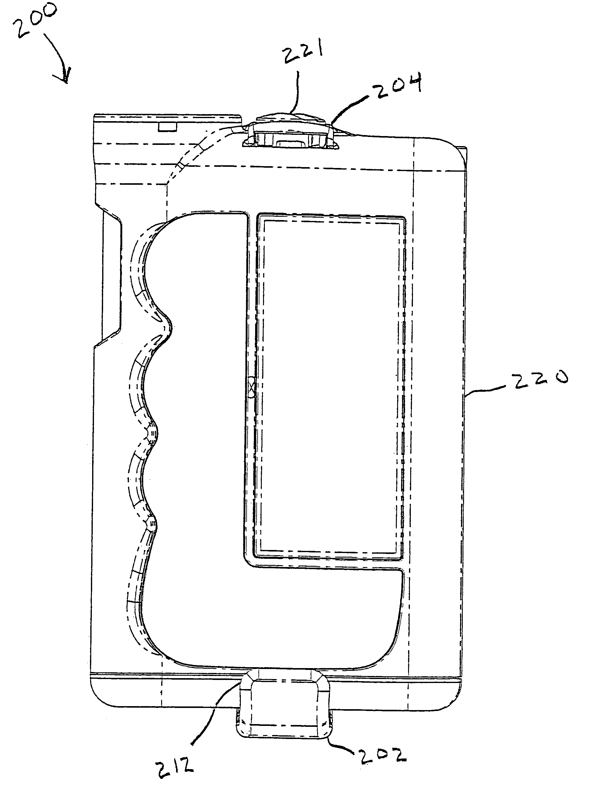
[0052]As discussed above, embodiments of the present invention relate to low-profile, durable mounting clips for holding personal devices (such as, but not limited to, personal medical devices, personal electronic devices, infusion devices (such as infusion pumps, disposable pumps, constant flow devices, or the like), medical monitors, or the like). In particular embodiments, a mounting clip having an essentially inverted “L” shaped configuration includes a wide foot portion including engagement elements for attachment to corresponding engagement elements on a housing of a personal device. The mounting clip further includes a leg portion for attachment to an ...


PUM


Abstract

A low-profile, durable mounting clip for holding personal devices. The mounting clip may have an essentially inverted “L” shaped configuration including a foot portion having engagement elements for attachment to corresponding engagement elements on a housing of a personal device. A leg portion provides for attachment to an undergarment or other suitable article of clothing. A heel portion located between and connecting the leg portion and foot portion allows the foot portion to flexibly and durably retract from the housing. The mounting clip may include a snap tab beam locking mechanism having a barb for interlocking with a bump provided on the housing or a rotatable cam locking mechanism having one or more radial snap tabs having engagement elements for engaging corresponding surfaces on the mounting clip. The mounting clip may have an essentially inverted “C-shaped” configuration including a first foot, a second foot, and a leg portion.

Description

CROSS REFERENCE TO RELATED APPLICATION[0001]This application is a continuation-in-part of U.S. patent application Ser. No. 10 / 021,885, entitled “LOW-PROFILE MOUNTING CLIP FOR PERSONAL DEVICE,” filed Dec. 14, 2001 now U.S. Pat. No. 6,665,909, assigned to Medtronic MiniMed, Inc., the contents of which are hereby incorporated by reference herein and from which priority is claimed.BACKGROUND OF THE INVENTION[0002]1. Field of the Invention[0003]The present invention relates, generally, to low-profile durable mounting clips for receiving and supporting personal devices (such as personal electronic devices) and, in particular embodiments, to low-profile mounting clips for inconspicuously holding a personal electronic device such as, but not limited to, an infusion device, a medical monitor or other medical device, in a concealed location by attaching the mounting clip to an article of clothing.[0004]2. Description of Related Art[0005]Various personal devices (such as personal electronic de...

Claims


Application Information

Patent Timeline
Patent Type & Authority Patents(United States)
IPC IPC(8): A45F5/02A61M5/142
CPCA45F5/02A45F5/021Y10T24/1394A61M5/14244Y10T24/13A45F2200/0516
Inventor COLLINS, SEANMOBERG, SHELDON B.KIMBALL, DAVID S.PAYNE, TIMOTHY J.SHETLER, LANCE E.
Owner MEDTRONIC MIMIMED INC
Why Eureka
Try Eureka