Gondola railcar construction

a railcar and gondola technology, applied in the direction of railway bodies, underframes, wagons/vans, etc., can solve the problems of extreme abuse of mill gondola cars, the inability of most cars to have interior bracing, etc., and achieve the effect of strengthening the gondola car and high strength connection

Inactive Publication Date: 2005-12-27
JOHNSON KENT N
View PDF13 Cites 39 Cited by
  • Summary
  • Abstract
  • Description
  • Claims
  • Application Information

AI Technical Summary

Benefits of technology

[0010]Generally described, the invention provides for a high strength connection between the side and the underframe for a mill car. The side posts are connected to a typical cross bearing member or bolster. A top cover portion of the cross bearing or bolster extends around the inside face of the post with a cutout that partially or completely surrounds the post. Connecting the side post directly to the cross bearing member in this manner provides a simple, high strength connection that addresses the main area of structural failure of mill cars of this type.
[0015]Accordingly, the present invention provides a high strength connection between the side posts and the underframe for a mill gondola car. The connection advantageously strengthens the gondola car without the need for internal bracing.

Problems solved by technology

Because of the types of loads carried and the manner of unloading cars such as with clam shell buckets or magnets, most cars cannot have any interior bracing.
Experience has shown that mill gondola cars are subject to extreme abuse, with most typical structural failures occurring at the connection of the side to the underframe at the side post interface.
Because typically no internal lateral reinforcement is used in a mill gondola car, lateral loads on the side walls of the car tend to tear the side posts away from the subframe assembly.
The loading / unloading buckets impact the car bodies much like mill gondolas causing substantial damage.
Because internal bracing is disfavored in these type of cars, the lateral loads have to be transferred down the posts into the underframe.

Method used


Image

  • Gondola railcar construction
  • Gondola railcar construction
  • Gondola railcar construction

Examples


Embodiment Construction

[0031]The present invention now will be described more fully hereinafter with reference to the accompanying drawings, in which preferred embodiments of the invention are shown. This invention may, however, be embodied in many different forms and should not be construed as limited to the embodiments set forth herein; rather, these embodiments are provided so that this disclosure will be thorough and complete, and will fully convey the scope of the invention to those skilled in the art. Like numbers refer to like elements throughout.

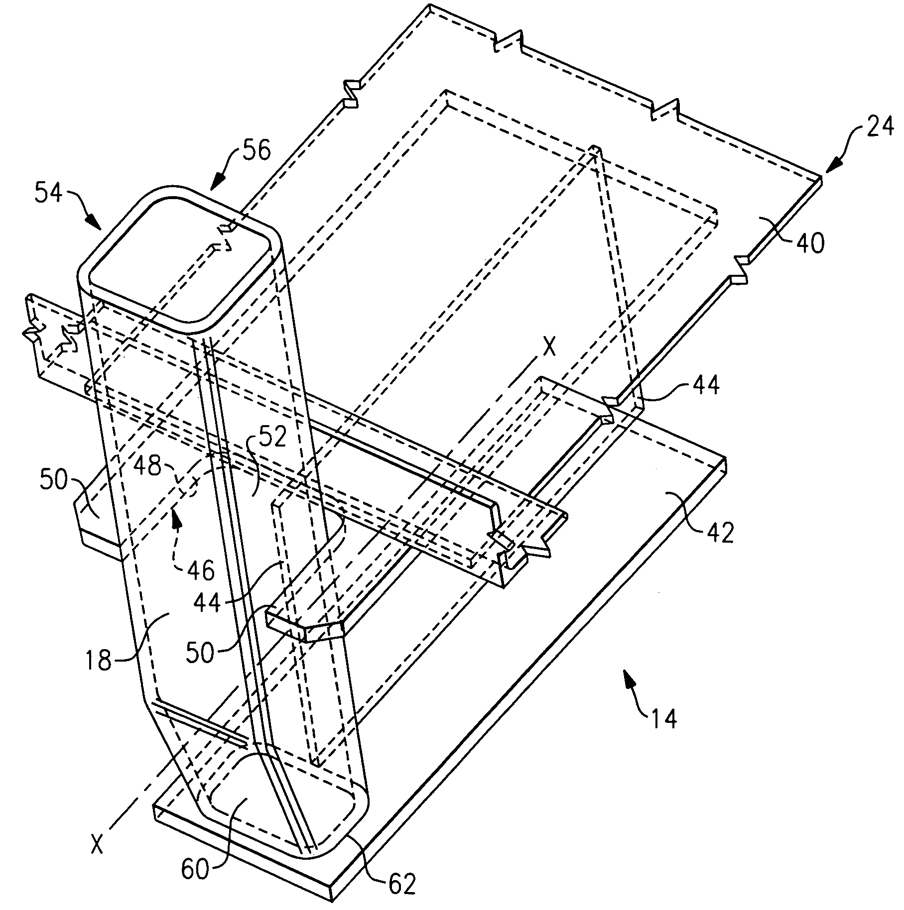
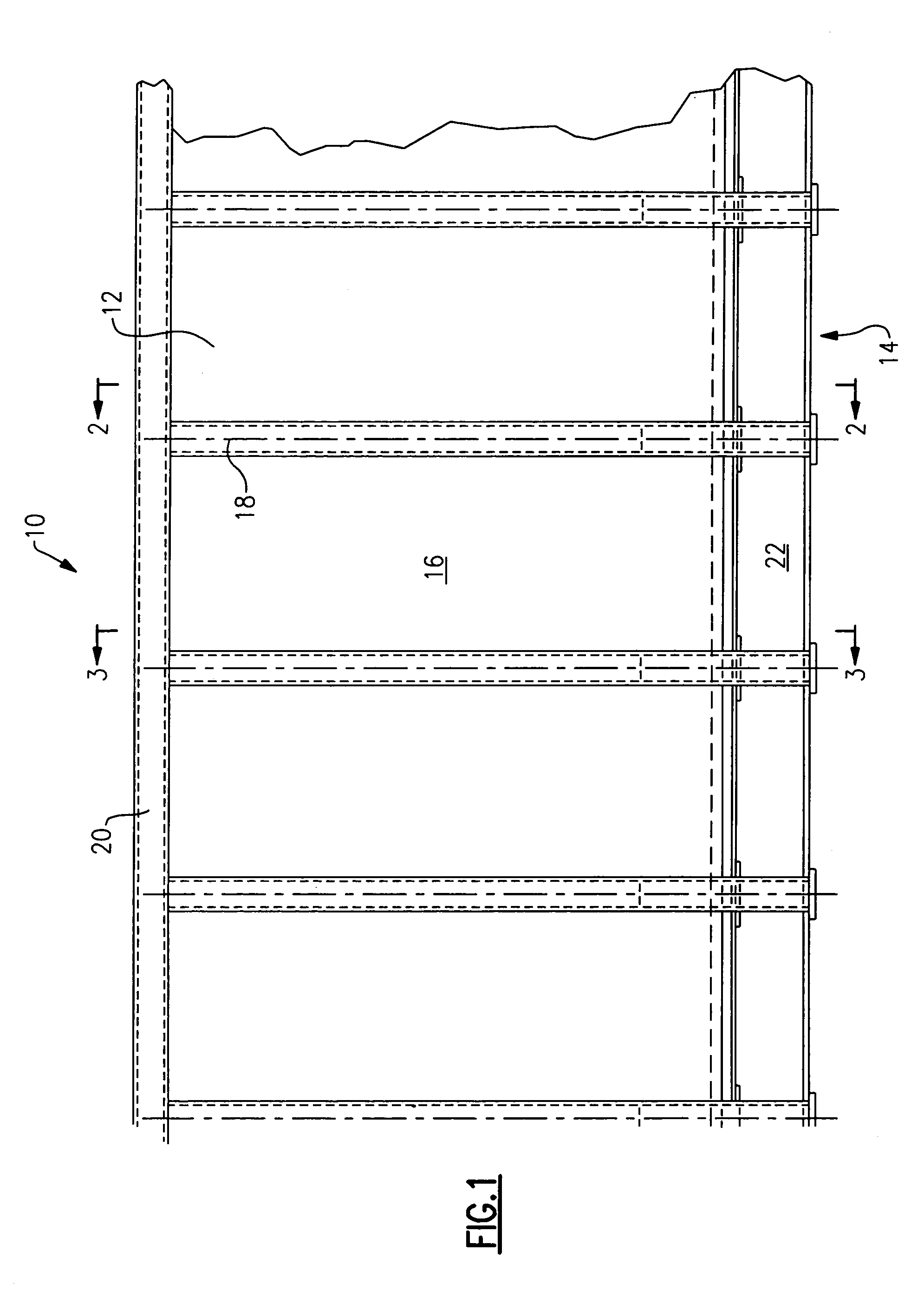
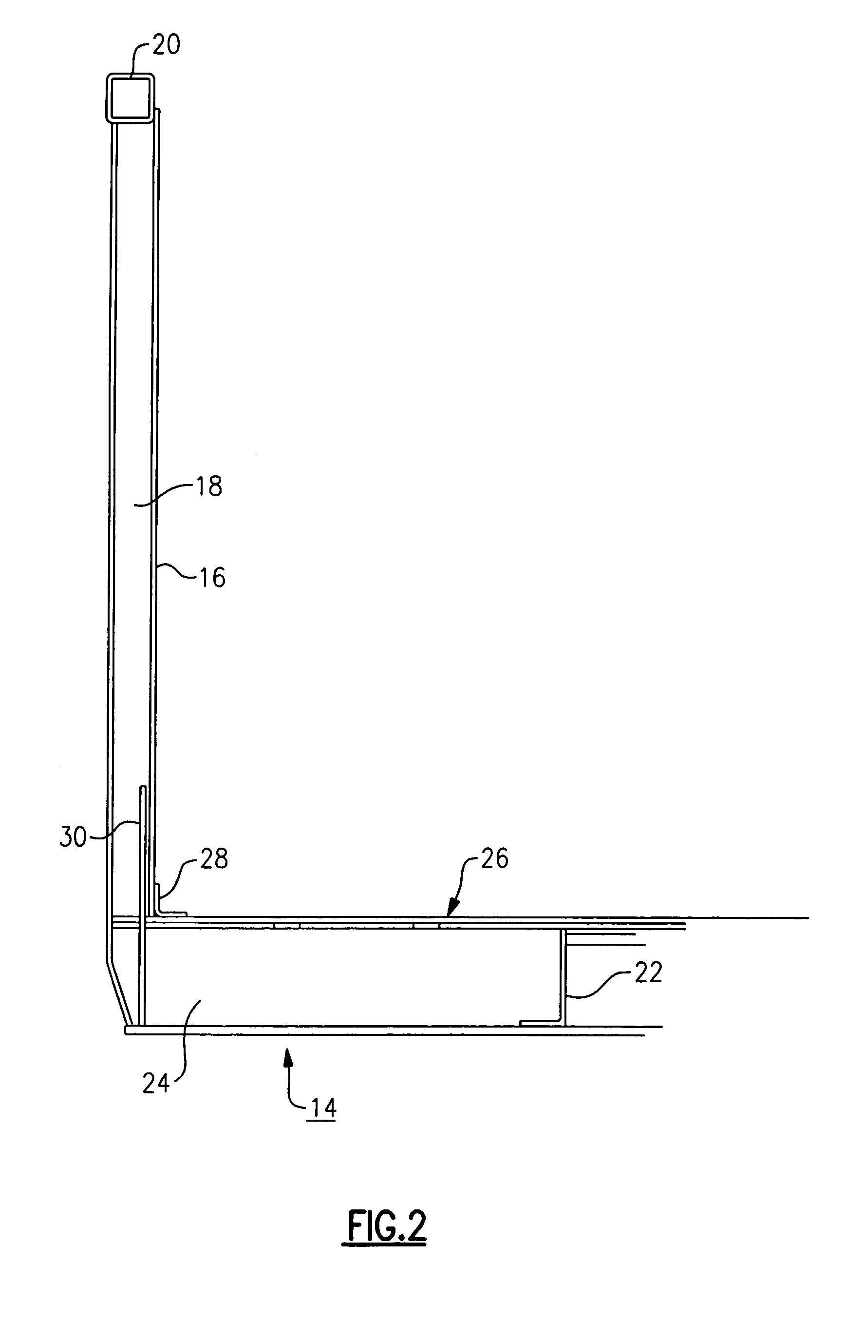
[0032]Referring to FIG. 1, a gondola car generally designated 10 includes a side frame assembly 12 and a subframe or underframe assembly 14. The side frame assembly 12 includes a side sheet 16 of a suitable thickness and material such as ¼″ steel sheet that extends along the length of the car and is of an appropriate height for the density of the commodities to be transported and the gross rail capacity of the vehicle. The side frame assembly 12 also inclu...


PUM


Abstract

A gondola railcar having a plurality of side posts connected to the underframe for a high strength construction. The underframe includes a plurality of cross-bearing members having an upper flange, a lower flange and at least one vertical web connecting the two flanges. The upper flange has an opening disposed therein that receives the side post such that the side post abuts with the upper flange inside the opening. The side post also abuts with an end of the vertical web, and an end portion of the side post abuts with the lower flange of the cross-bearing member.

Description

FIELD OF INVENTION[0001]This invention relates to a railroad gondola car, and particularly an improved railroad gondola car having enhanced lateral load strength, especially in the area of the connection between the side walls of the car and the subframe.BACKGROUND OF THE INVENTION[0002]A number of different types of railroad cars are available, particularly categorized according to the type of cargo for which they are intended. The type of cargo dictates a number of requirements such as cubic foot capacity, floor strength, side wall strength, covered or uncovered, and so forth.[0003]Gondola cars are typically open or uncovered vehicles and are used to carry a large variety of industrial cargo. But even within the category of gondola railcars, several different types are available, again depending upon the type of cargo to be handled. Specifically, some gondola cars are designed to carry wood chips and similar products of relatively low density, while other gondola cars carry such p...

Claims


Application Information

Patent Timeline
Patent Type & Authority Patents(United States)
IPC IPC(8): B61D17/08B61F1/12
CPCB61D17/08B61F1/12
Inventor JOHNSON, KENT N.
Owner JOHNSON KENT N
Why Eureka
Try Eureka