Vessel transfer system and associated methods

a technology of transfer system and transfer vessel, which is applied in the direction of waterborne vessels, vertical ship lifting, construction, etc., can solve the problems of high installation cost, time-consuming construction, and difficulty in transferring vessels from one water level to another, and achieve the effect of easy installation and energy-saving

Active Publication Date: 2005-12-27
THOMPSON KENNETH R
View PDF21 Cites 18 Cited by
  • Summary
  • Abstract
  • Description
  • Claims
  • Application Information

AI Technical Summary

Benefits of technology

[0008]In view of the foregoing background, it is therefore an object of the present invention to provide a practical energy efficient, and time efficient system for transferring a vessel between a first body of water and second body of water separated by a barrier that may be readily installed adjacent an existing barrier. It is further an object of the present invention to provide a system for transferring a vessel between a first body of water and second body of water without lifting the vessel out of the water. It is still another object of the present invention to provide a system for transferring a vessel between a first and second body of water that is secure.
[0011]The system may also include a counterweight apparatus. The counterweight apparatus may comprise at least one variable engagement member in communication with the at least one cable engagement rod, at least one weight, and a length of cable connected between the weight, the at least one variable engagement member, and the cable engagement rod. Accordingly, the transfer structure may advantageously be moved between the first and second positions in a time efficient and energy efficient manner.

Problems solved by technology

One disadvantage that exists with boating communities that have such marina pools, however, is that in order for the vessel to be used in the adjacent navigable waterway, it must first be transferred from the marina pool to the navigable waterway.
This system, however, may be quite expensive and complicated to install, as well as time consuming to construct.
Further, using such a system to transfer a vessel from one water level to another may be very slow.
Again, this system may be very expensive, complicated, and time consuming to install, and may also be slow to transfer a vessel between two bodies of water.

Method used


Image

  • Vessel transfer system and associated methods
  • Vessel transfer system and associated methods
  • Vessel transfer system and associated methods

Examples


Embodiment Construction

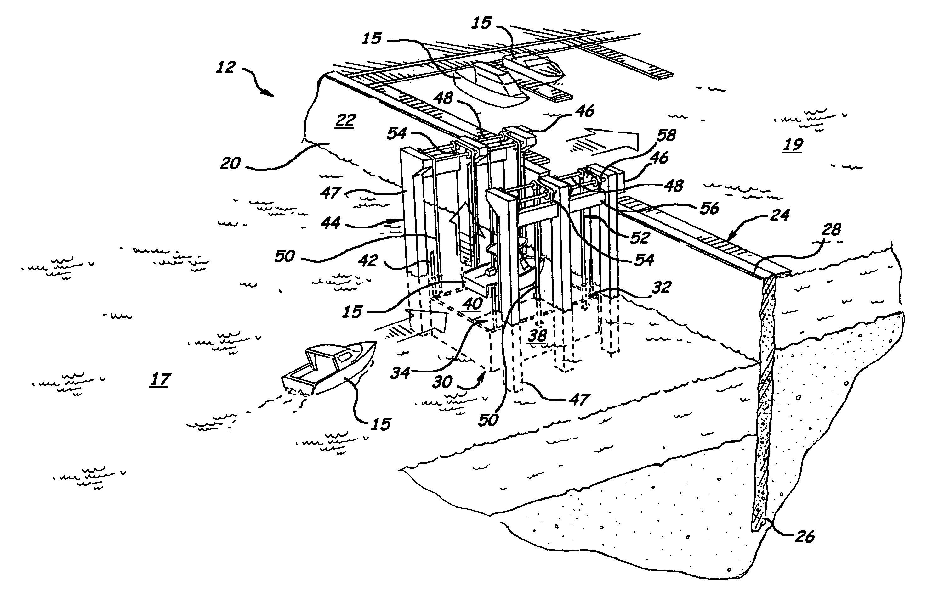
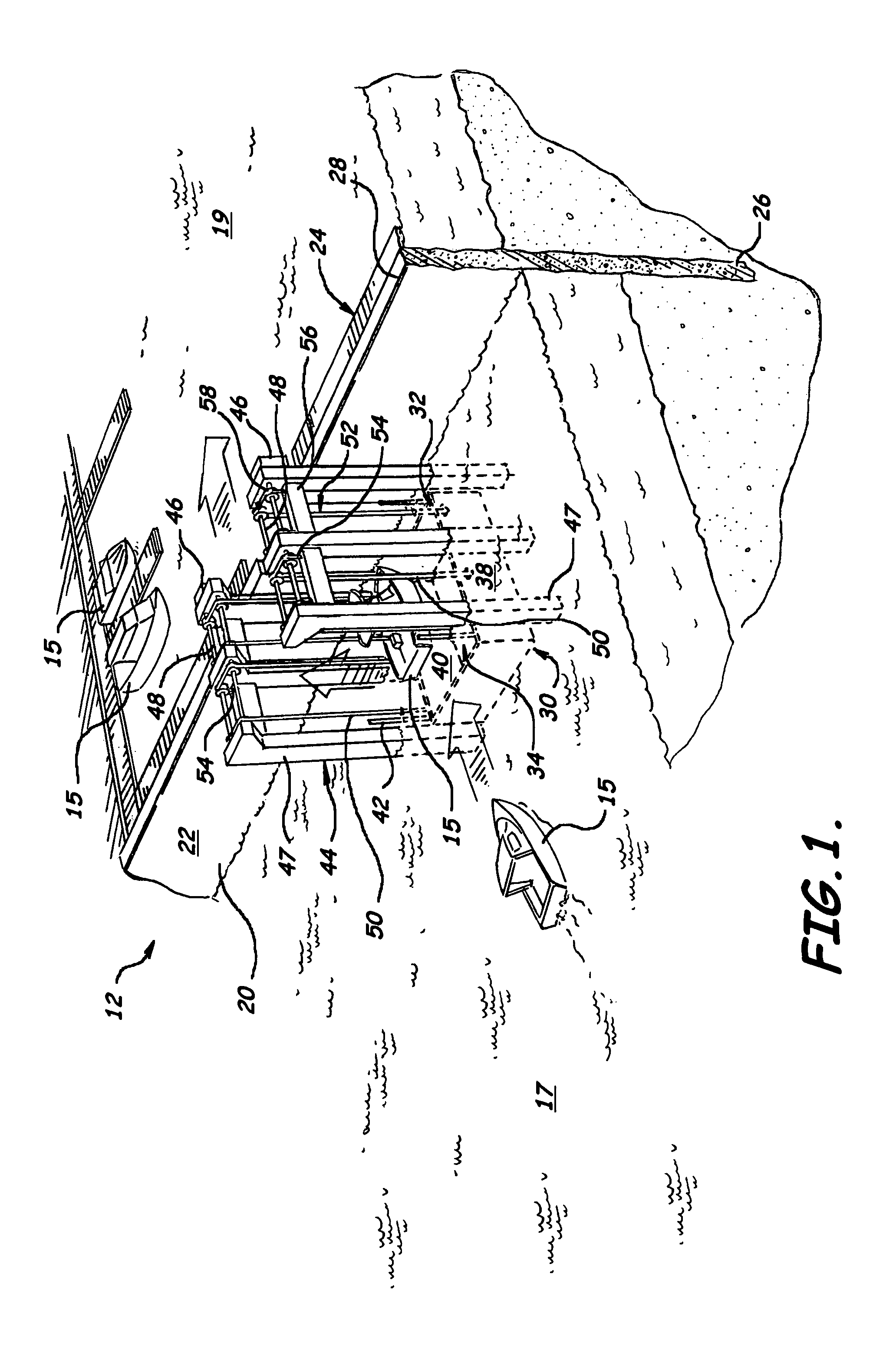
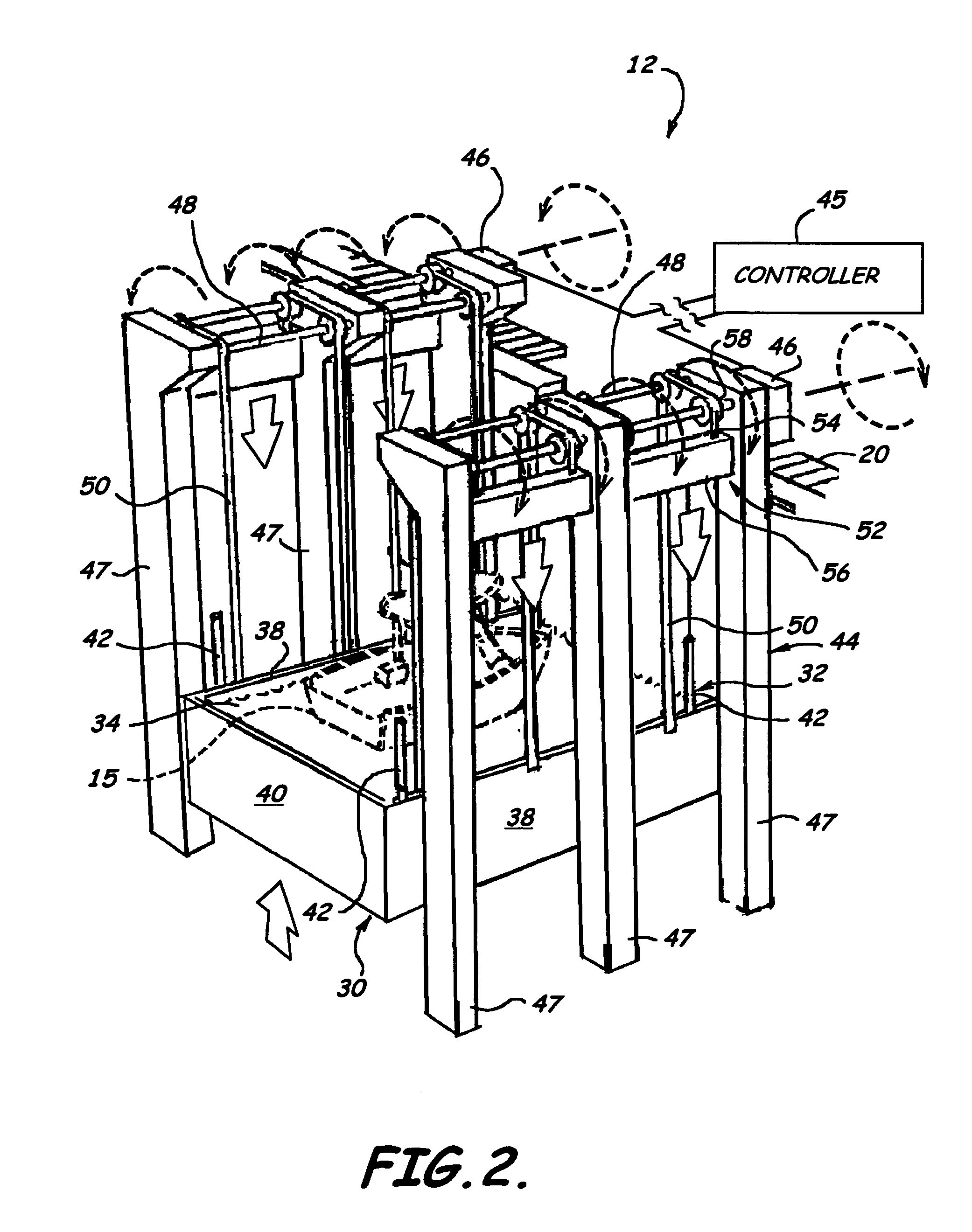
[0026]The present invention will now be described more fully hereinafter with reference to the accompanying drawings, in which preferred embodiments of the invention are shown. This invention may, however, be embodied in many different forms and should not be construed as limited to the embodiments set forth herein. Rather, these embodiments are provided so that this disclosure will be thorough and complete, and will fully convey the scope of the invention to those skilled in the art. Like numbers refer to like elements throughout, and prime and multiple prime notations are used to indicate similar elements in alternate embodiments.

[0027]Referring initially to FIGS. 1–4C, a system 12 for transferring a vessel 15 between a first body of water 17 and a second body of water 19 is now described. The first body of water 17 may, for example, be a navigable waterway, and the second body of water 19 may be a waterway adjacent the navigable waterway, such as a marina pool for a boating commu...


PUM


Abstract

A system for transferring a vessel between a first body of water having a first water level and a second body of water having a second water level includes a barrier separating the first body of water from the second body of water. The system also includes a transfer structure adjacent the barrier for receiving the vessel to be transferred between the first and second bodies of water, and a transfer apparatus adjacent the barrier for moving the transfer structure between a first position and a second position. The upper portion of the barrier includes a barrier door that is movable between an opened position when the transfer structure is in the second position to allow the vessel to move into and out of the transfer structure, and a closed position when the transfer structure is in the first position.

Description

FIELD OF THE INVENTION[0001]The present invention relates to the field of transferring vessels, and, more particularly, to the field of transferring vessels between a navigable waterway, and a private waterway, and related methods.BACKGROUND OF THE INVENTION[0002]Boating communities may sometimes have marina pools so that residents may keep their vessels in the water. These marina pools are generally constructed adjacent a navigable waterway. Further, a barrier generally separates the marina pool from the adjacent navigable waterway. There are many advantages to marina pools, such as a more protected environment for keeping a vessel in water, for example.[0003]One disadvantage that exists with boating communities that have such marina pools, however, is that in order for the vessel to be used in the adjacent navigable waterway, it must first be transferred from the marina pool to the navigable waterway. More particularly, the marina pool may have a first water level, and the navigab...

Claims


Application Information

Patent Timeline
Patent Type & Authority Patents(United States)
IPC IPC(8): E02C5/00
CPCE02C5/00
Inventor THOMPSON, KENNETH R.
Owner THOMPSON KENNETH R
Why Eureka
Try Eureka