
Central speed control mechanism for remote control cars

a technology of central speed control and remote control, which is applied in the direction of remote control toys, toys, entertainment, etc., can solve the problems of difficult to dispose of assembled elements into the housing, and not generate the best twist force, and achieve the effect of preferred damping effect for speed adjustmen

Inactive Publication Date: 2005-12-27
CHU DAIMLER
View PDF9 Cites 4 Cited by
  • Summary
  • Abstract
  • Description
  • Claims
  • Application Information

AI Technical Summary

Benefits of technology

"The invention is a central speed control mechanism for remote control cars that can generate a stopping force to control the speed adjustment. It is designed to be easily assembled and constructed. The mechanism includes a housing and a cover with a pivot for connecting to the remote control car. Inside the housing, there is a gear set consisting of a positioning block, bevel gears, and axles. The axle holes are provided on the positioning block, while the bevel gears have conical surfaces that match with the axle's conical surface. The bevel gears engage with the helical gears of the pivots. When the speed controller rotates at high speeds, the bevel gears' conical surfaces match with the axle's conical surface to create a damping force, which helps to control the speed of the remote control car."

Problems solved by technology

Remote control cars are popular to children and adults as well since they are easy controlled and quite challenging for entertainment purposes.
However, as the engagement of the helical gears C1 appears a parallel way, it cannot generate the best twist force.
Therefore, there exists a disadvantage of the prior art, i.e. it is difficult to dispose the assembled elements into the housing.

Method used


Image

  • Central speed control mechanism for remote control cars
  • Central speed control mechanism for remote control cars
  • Central speed control mechanism for remote control cars

Examples


Embodiment Construction

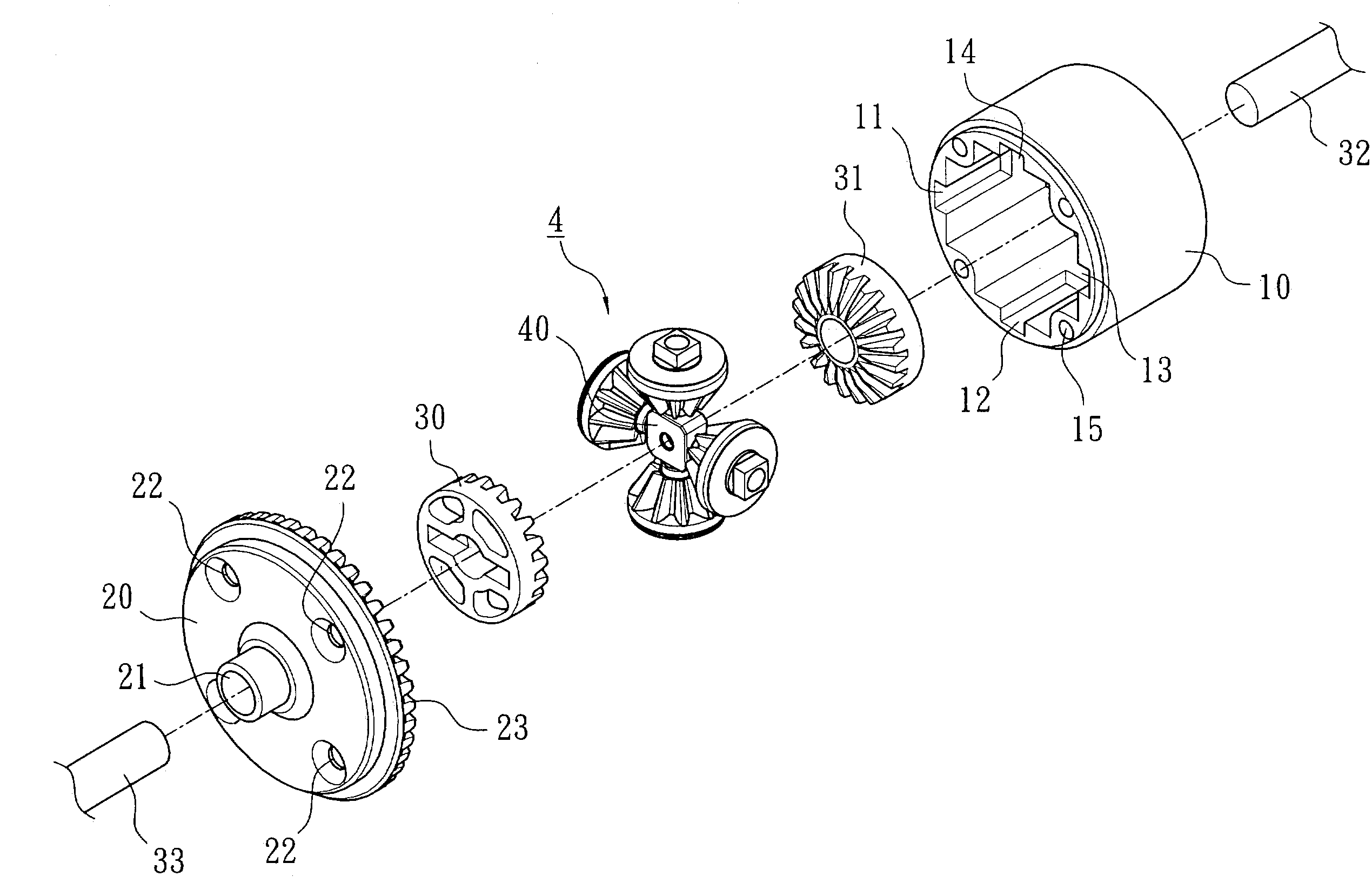
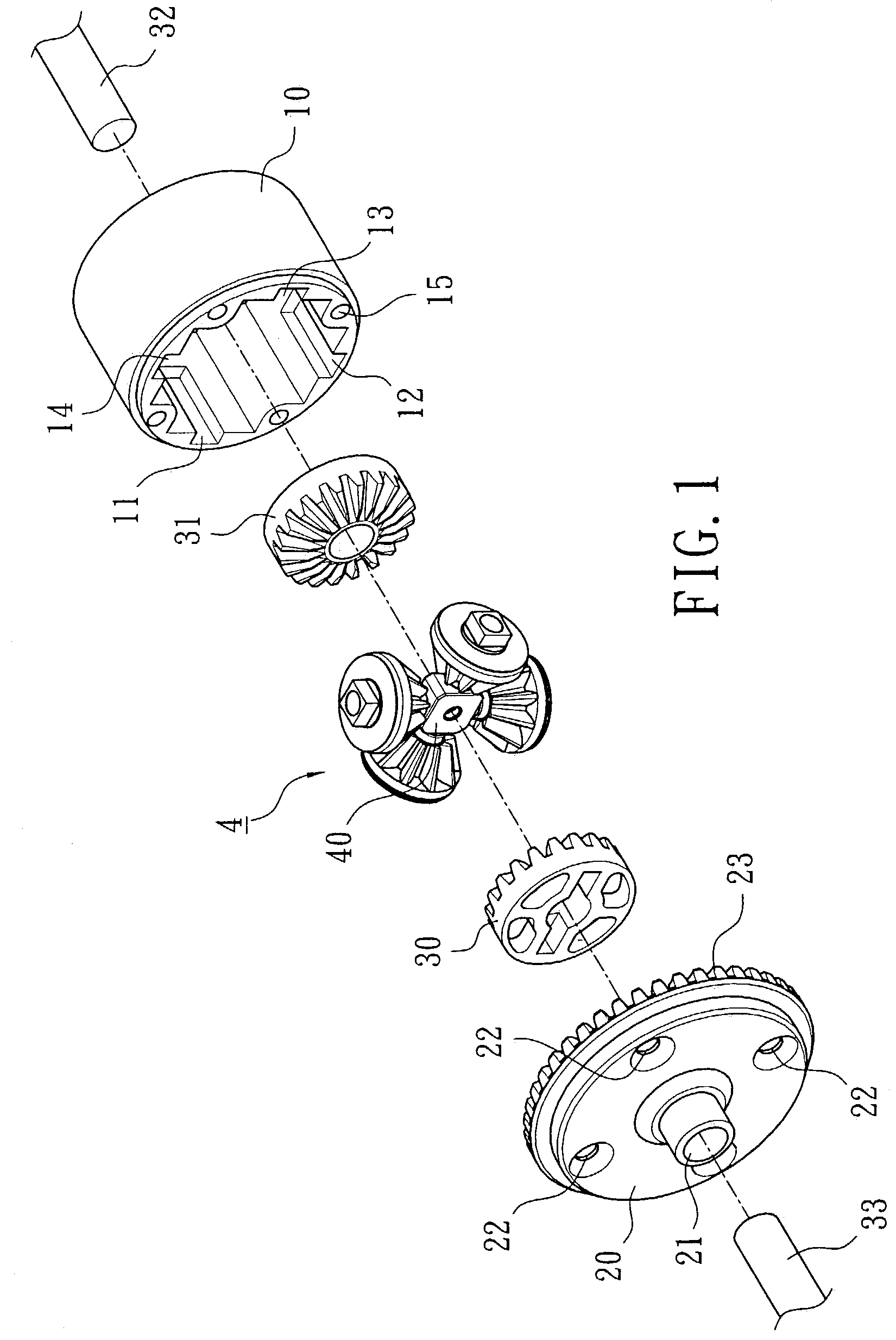
[0016]As shown in FIG. 1, the present invention primarily comprises a housing 10, a cover 20 and a gear set 4. Corresponding grooves 11, 13 and 12, 14 are provided on the inner wall of the housing 10. And locking holes 15 are provided in-between every two grooves. A pivot hole (not shown) is provided on the central bottom of the housing 10, such that a pivot 32 can pass through the housing 10 and connect to the wheel of the remote control car (not shown) with one end, and connect to a helical gear 31 with another end.

[0017]The cover 20 is connectable to the housing 10. A pivot hole 21 is provided on the center of the cover 20, whereas a plurality of locking holes 22 are provided on the periphery thereof. The housing 10 and the cover 20 can be assembled by way of screwing a plurality of screws (not shown) into the locking holes 22.

[0018]Inside of the pivot hole 21 is provided with a pivot 33 which is connected to the wheel (not shown) at one end and to a helical gear 30 an the other ...


PUM


Abstract

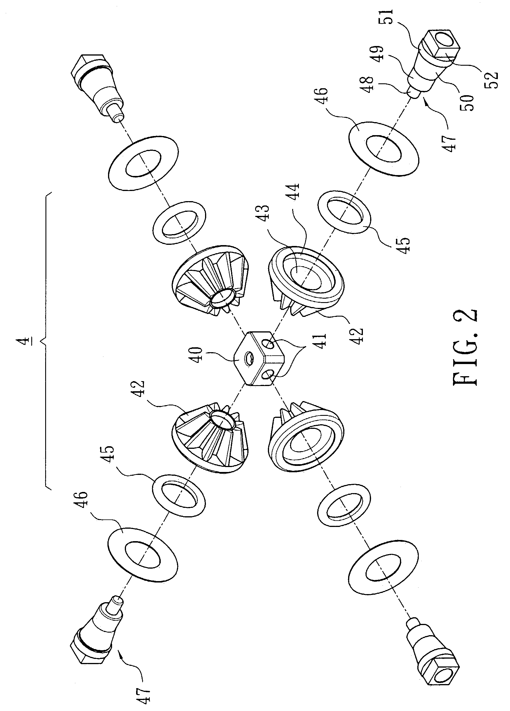
An improved central speed control mechanism for remote control cars primarily comprises a housing and a cover, which are connectable to each other and are respectively provided with a pivot for connecting to the remote control car at one end and mounting helical gears at the other end. Inside of the housing is provided with a gear set, which comprises a positioning block, a plurality of bevel gears and axles. Axle holes are equally provided on the periphery of the positioning block, whereas a central hole with a cone surface is provided in the bevel gears for matching with the cone surface of the axle which is provided with a positioning pillar at the front end and a cone surface in the middle section. After the axle passes the end of the bevel gear provided with a O-ring through to the axle hole, and a washer is further provided at the rear of the axle to complete the assembly of the whole housing, the plurality of bevel gears of the gear set will engage with the helical gears of the two pivots.

Description

BACKGROUND OF THE INVENTION[0001]1. Field of the Invention[0002]The present invention relates to an improved central speed control mechanism for remote control car, which may generate an appropriate stopping force to make better speed adjustment, and is particularly applicable to remote control cars, model cars and the like.[0003]2. Description of the Prior Art[0004]Remote control cars are popular to children and adults as well since they are easy controlled and quite challenging for entertainment purposes. A speed controller is very important to remote control cars, no matter they are simple or complex structures. The speed controllers of the prior art (as shown in FIG. 6) primarily comprise a housing A provided with four worm gears C. Each of the worm gear C is provided with a helical gear C1 at the upper and lower end, whereas two axles B provided with worm gear B1 at the end are disposed in-between the worm gears C, such than when the axles B rotate, the worm gears C engage with...

Claims


Application Information

Patent Timeline
Patent Type & Authority Patents(United States)
IPC IPC(8): A63H29/22A63H30/00
CPCA63H29/22A63H30/00
Inventor CHU, DAIMLER
Owner CHU DAIMLER
Learn More