
Developing cartridge

a technology of developing cartridges and cartridges, applied in the field of developing cartridges, can solve problems such as toner leakage, and achieve the effects of preventing leakage, good transference, and limiting the adhesion of toner

Inactive Publication Date: 2005-12-27
BROTHER KOGYO KK
View PDF10 Cites 31 Cited by
  • Summary
  • Abstract
  • Description
  • Claims
  • Application Information

AI Technical Summary

Benefits of technology

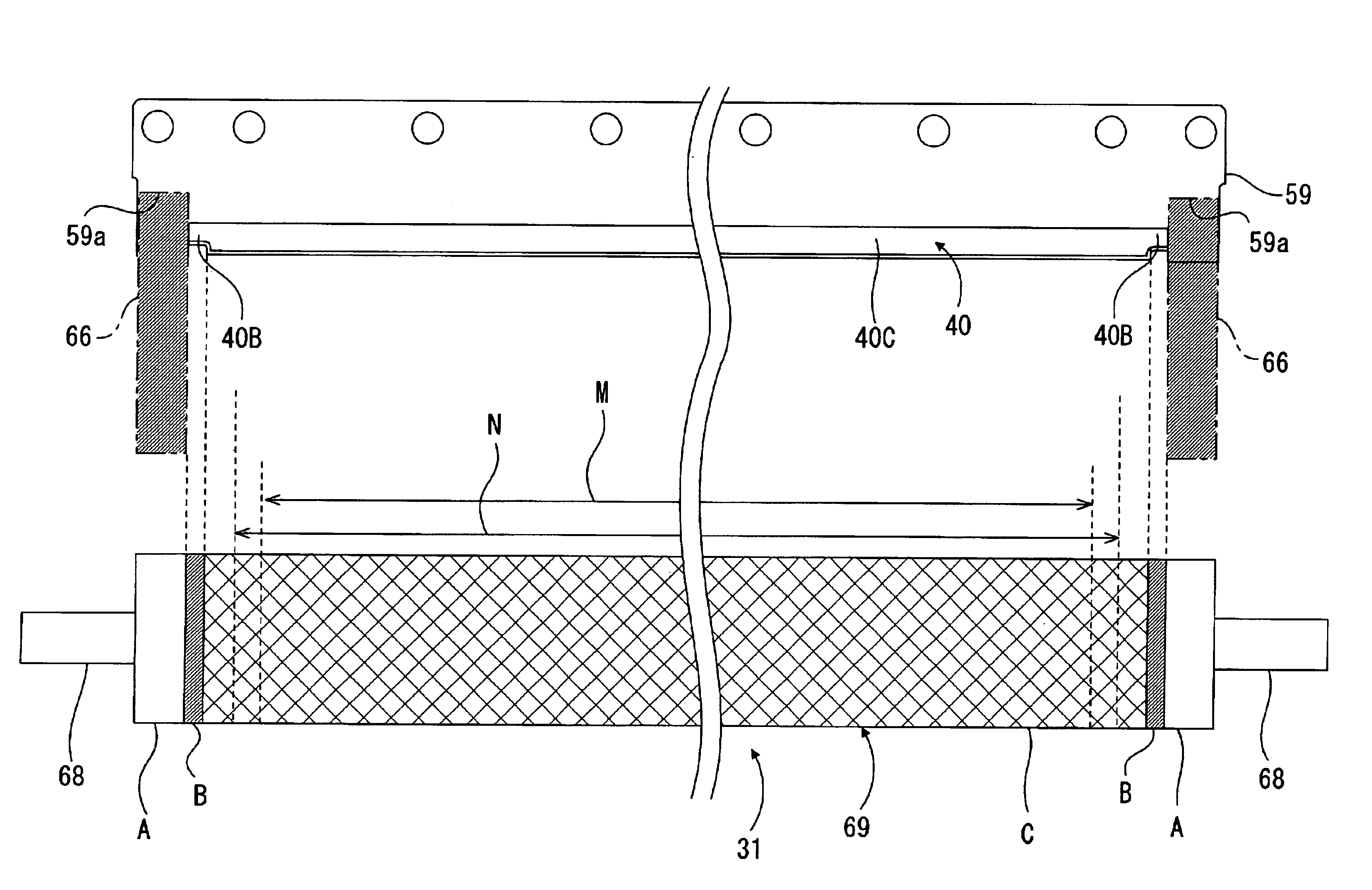
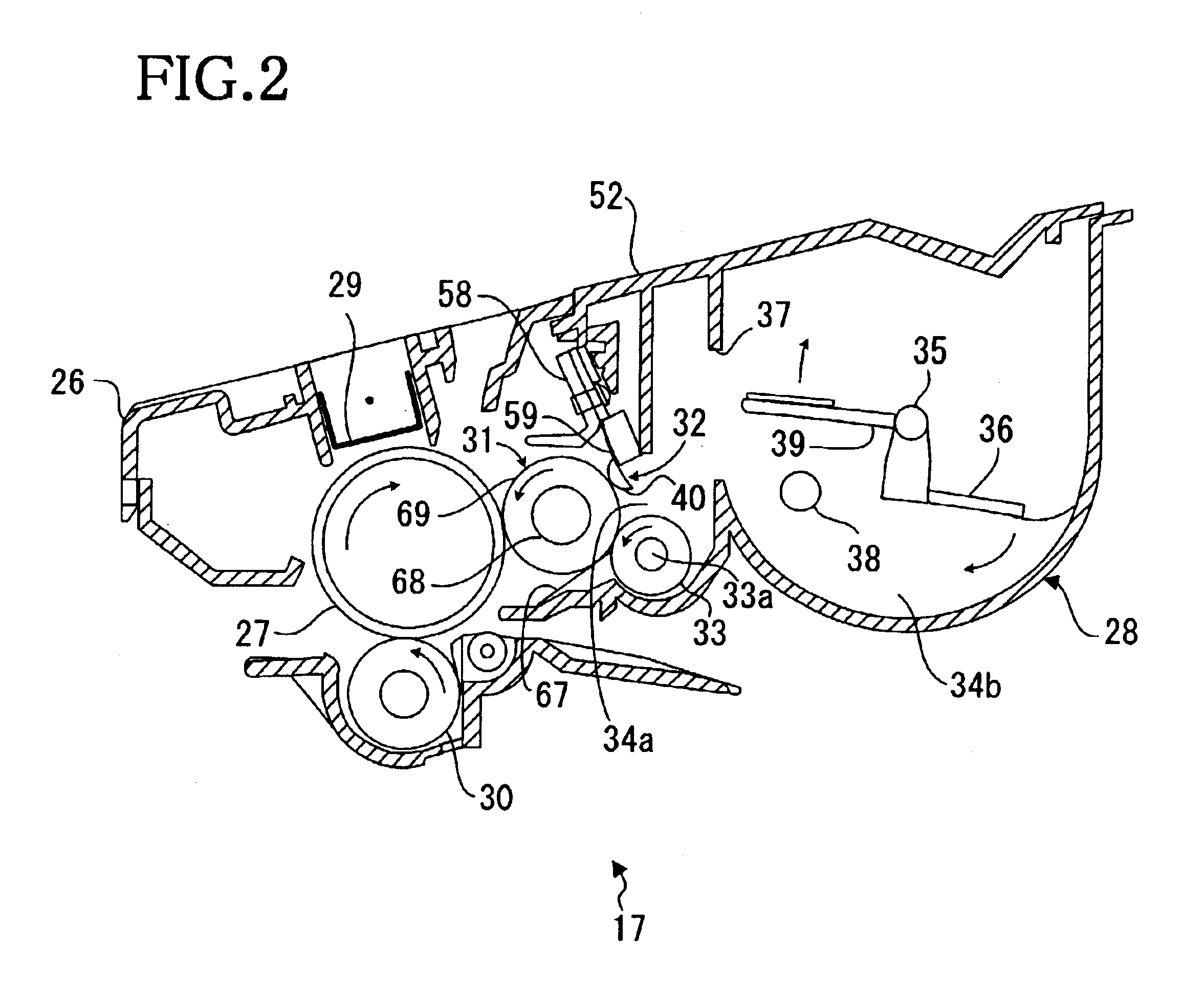
The invention is a developing cartridge for a printer that has a roller for carrying developer to the paper. The roller is divided into three regions: seal regions at the ends, a side-end region in the middle, and a center region. The seal regions make contact with side seals in the housing. A blade is also included to regulate the thickness of toner on the roller. The surface roughness and hardness of the roller are different in the different regions, resulting in a thinner layer of toner on the side-end region and a thicker layer in the center region. This results in better transfer of toner to the paper and higher quality images.

Problems solved by technology

If the laser printer is used for a long term, toner held at both ends of the developing roller, especially near side seals, is scraped off by the side seals by the rotation of the developing roller and may result in toner leakage.

Method used


Image

  • Developing cartridge
  • Developing cartridge
  • Developing cartridge

Examples


Embodiment Construction

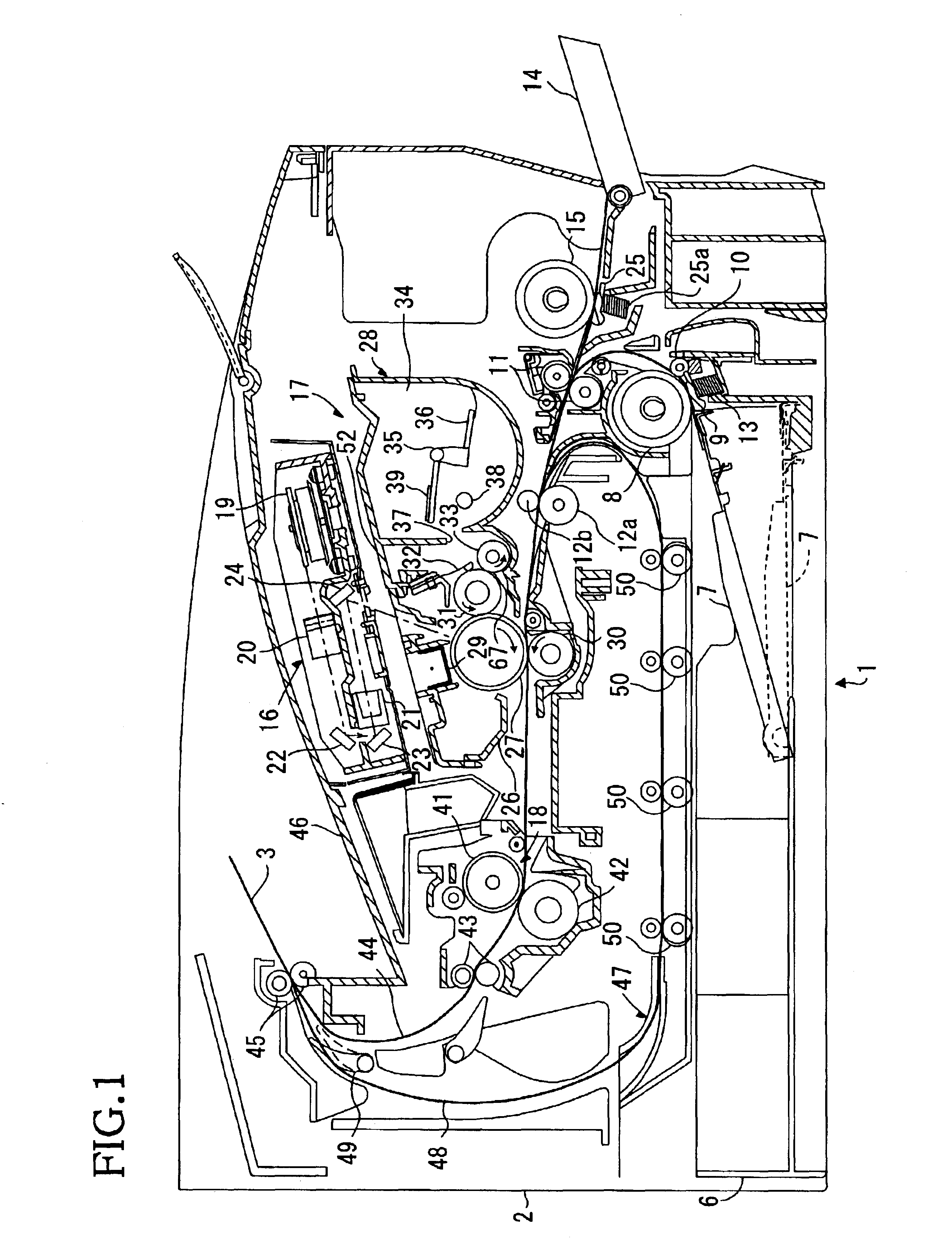
[0028]FIG. 1 is a side sectional view of the major parts of a laser printer 1 according to an embodiment of the invention. A sheet feed tray 6 is detachably attached to a bottom portion of a casing 2. A presser plate 7 is provided in the sheet feed tray 6 so as to support and upwardly press sheets 3 stacked in the sheet feed tray 6. A sheet feed roller 8 and a sheet feed pad 9 are provided above one end of the sheet feed tray 6, and register rollers 12 are provided downstream from the sheet feed roller 8 with respect to the sheet conveying direction.

[0029]The presser plate 7 allows sheets 3 to be stacked thereon. The presser plate 7 is pivotally supported at its end remote from the sheet feed roller 8 such that the presser plate 7 is vertically movable at its end closer to the sheet feed roller 8. The presser plate 7 is urged upwardly from its reverse side by a spring (not shown). When the stack of sheets 3 is increased in quantity, the presser plate 7 swings downwardly about the en...


PUM


Abstract

A developing cartridge has a housing that accommodates developer therein. Rotatably mounted in the housing is a developing roller. The housing has side seals provided at each end of the developing roller that oppose the circumferential ends of the developing roller. The developing roller itself is divided into a seal region, a side-end region and a center region. A portion of the seal region and the side-end region found at each end of the developing roller with the seal region portions being at the ends of the roller and the side end region portions being between the seal region portions and the center region. Opposing the developing roller is a toner thickness regulating blade having a presser portion. The presser portion has a discontinuous cross-section such that a greater portion of the presser member contacts the developer roller in each portion of the side-end region then contacts the developer roller in the center region. As a result, a greater pressure is applied between the presser portion and the developer roller at the side-end region thereby resulting in less toner being applied to the developing roller to be carried to a photosensitive member. To further the minimize the amount of toner applied to the developing roller, the roughness in the side end region of the developing roller is smaller than the roughness in the center region and the hardness in the side end region of the developing roller is greater than the hardness in the center region. This combination of factors prevents toner from leaking from the housing at the ends of the developing rollers.

Description

BACKGROUND OF THE INVENTION[0001]1. Field of Invention[0002]The invention relates to a developing cartridge which is applied to a laser printer.[0003]2. Description of Related Art[0004]U.S. Pat. No. 6,336,014 discloses a structure in which a developing cartridge accommodating toner is detachably attached to a printer. The developing cartridge includes a developing roller that supplies toner to a photosensitive medium and a supply roller that makes contact with the developing roller to supply toner to the developing roller. A layer thickness-regulating blade, which regulates the thickness of a toner layer formed on the surface of the developing roller makes contact with a circumferential surface of the developing roller. A lower film is disposed at a lower part of the developing roller along an axial direction of the developing roller.[0005]The developing cartridge further includes side seals for preventing toner carried on the developing roller from leaking outside of the developing...

Claims


Application Information

Patent Timeline
Patent Type & Authority Patents(United States)
IPC IPC(8): G03G15/08
CPCG03G15/0817
Inventor KAMIMURA, NAOYA
Owner BROTHER KOGYO KK
Learn More