Device for installing a pre-hung door

a pre-hung door and device technology, applied in the field of pre-hung doors, can solve the problems of large surface area for bonding, large surface area for frame material, prone to twisting, warping, bending, etc., and achieve the effect of facilitating frame alignment and increasing or decreasing the width and length of the rectangl

Inactive Publication Date: 2006-01-03
WIDGET TOOLS
View PDF17 Cites 13 Cited by
  • Summary
  • Abstract
  • Description
  • Claims
  • Application Information

AI Technical Summary

Benefits of technology

[0010]Briefly, in accordance with the present invention, disclosed is a device for securely holding a pre-hung doorframe in a rough opening of a wall so that the frame can be properly secured to the wall in a straight and plumb alignment. The device includes four slidably adjustable elements arranged in a rectangular shape. Each element has a separation line near its center. A plate spans the separation line and has a groove along its length. Two bolts, one on either side of the separation line, extend in a direction toward the inner area of the rectangle and ride inside the groove in the plate when the elements are separated at the separation line. In this way, the rectangle can be increased or decreased in both width and length. Nuts on the ends of the bolts can be tightened to secure the elements in a particular position.
[0011]The device is placed inside a pre-hung doorframe and slidably adjusted to meet the inner dimensions of the frame. The device has pairs of clamps along its elements which are used to attach and secure the frame to the device so that the device and frame can be placed within a rough opening in a wall and the frame will retain the rectangular shape of the device without being able to distort. The clamps can be used to attach the device and frame to the edges of the rough opening of the wall to further facilitate alignment of the frame with the wall. Advantageously, the device is rectangularly shaped and is completely open within its center, allowing workers to pass unencumbered through the doorway when the device is in place.
[0012]The frame, still attached to the device, is then leveled within the rough opening. A pair of telescoping feet attached to the base of the device allow the frame to be spaced from the floor surface and tilted to ensure proper leveling within the rough opening. Once the frame is level, shims are placed at various locations between the outside surface of the frame and an inside surface of the rough opening in the wall to provide proper contact with the opening. The device is provided with pass-through holes so that a screw or nail can be inserted into the frame, the shims, and finally the inside surface of the rough opening in the wall, to secure the frame in its properly aligned location.

Problems solved by technology

However, the frame material is relatively thin and the four corners, where the rectangularly arranged sections meet and are attached to each other, do not present a great deal of surface area for bonding.
Therefore, the frame is prone to twisting, warping, bending, and separating during the installation stage.
If the frame is not completely square, the door will not swing true and will not close properly.
This can result in gaps between the door and the frame, the doors hitting the frame or floor, or not closing properly.
This method is difficult and time consuming even for a skilled carpenter.
Additionally, this method does not ensure that the frame is installed in a single plane.
The Tuthill apparatus, however, suffers from the disadvantage of only securing the frame to the apparatus in one direction with a frame member 110, allowing a section of the frame to slide out of skew during installation.
Additionally, the floor of the building may not be perfectly level, however, the door must be.
This presents a difficulty to the carpenter who may need to work from both sides of the doorway to install the frame.
It also prevents other workers from being able to pass through the opening while the device is in place, possibly slowing progress on other areas of the building.
The Cloutier et al. device also suffers from some of the same disadvantages as does the Tuthill device.
Secondly, the device does not provide a means for adjusting the height of the device, and therefore the frame, from the floor surface.
Additionally, the Cloutier et al. device suffers from the disadvantage that it is not vertically collapsible and is therefore difficult to move, store, and remove from the door opening after the frame is secured.
Finally, because the device is fixed in the vertical dimension, it cannot accommodate doors of varying size.
This particular disadvantage is shared by the doorframe-hanging devices disclosed in Torstensen (U.S. Pat. No. 6,530,186) and McKay (U.S. Pat. No. 2,502,166).

Method used


Image

  • Device for installing a pre-hung door
  • Device for installing a pre-hung door
  • Device for installing a pre-hung door

Examples


Embodiment Construction

[0031]While the specification concludes with claims defining the features of the invention that are regarded as novel, it is believed that the invention will be better understood from a consideration of the following description in conjunction with the drawing figures, in which like reference numerals are carried forward.

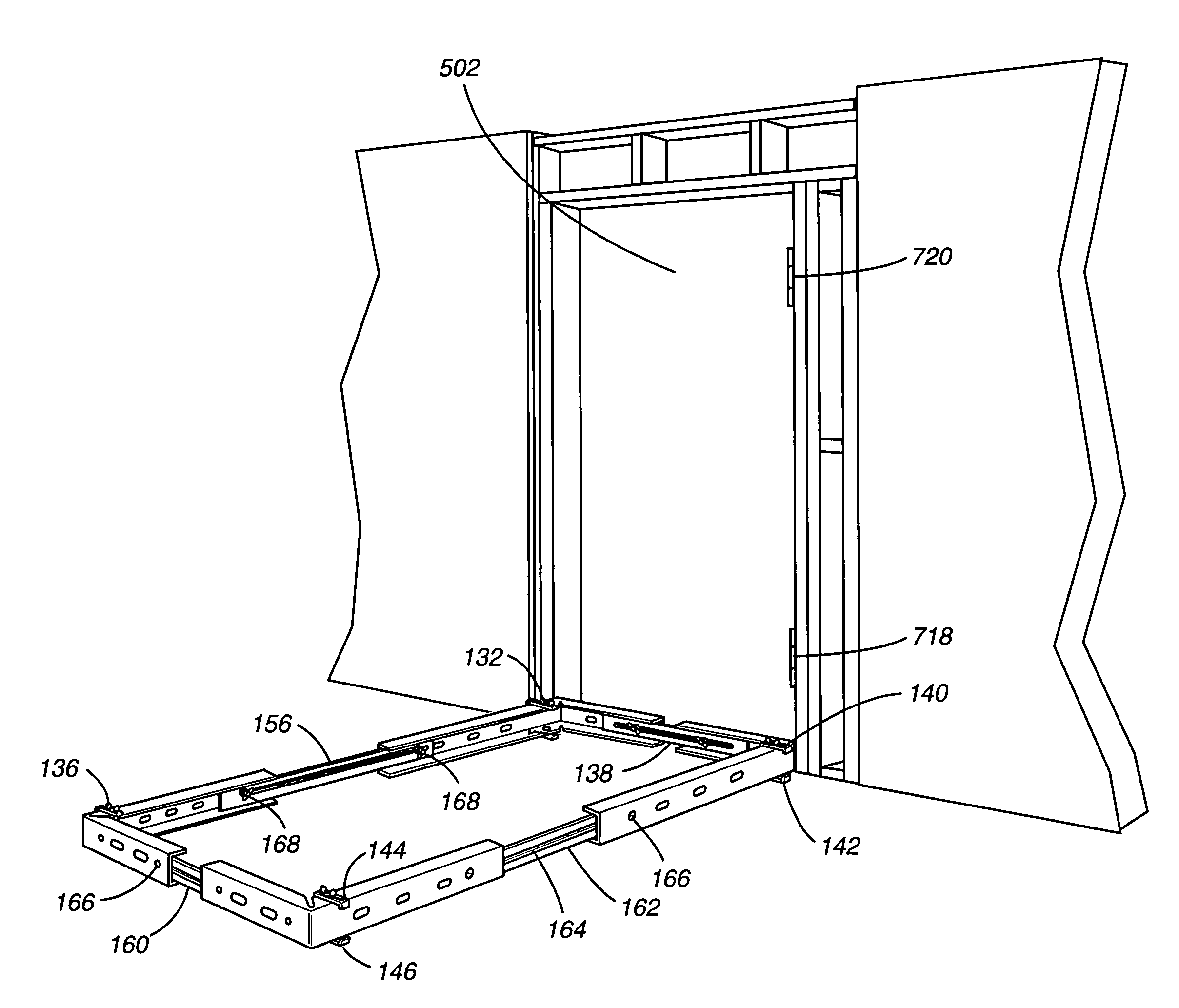
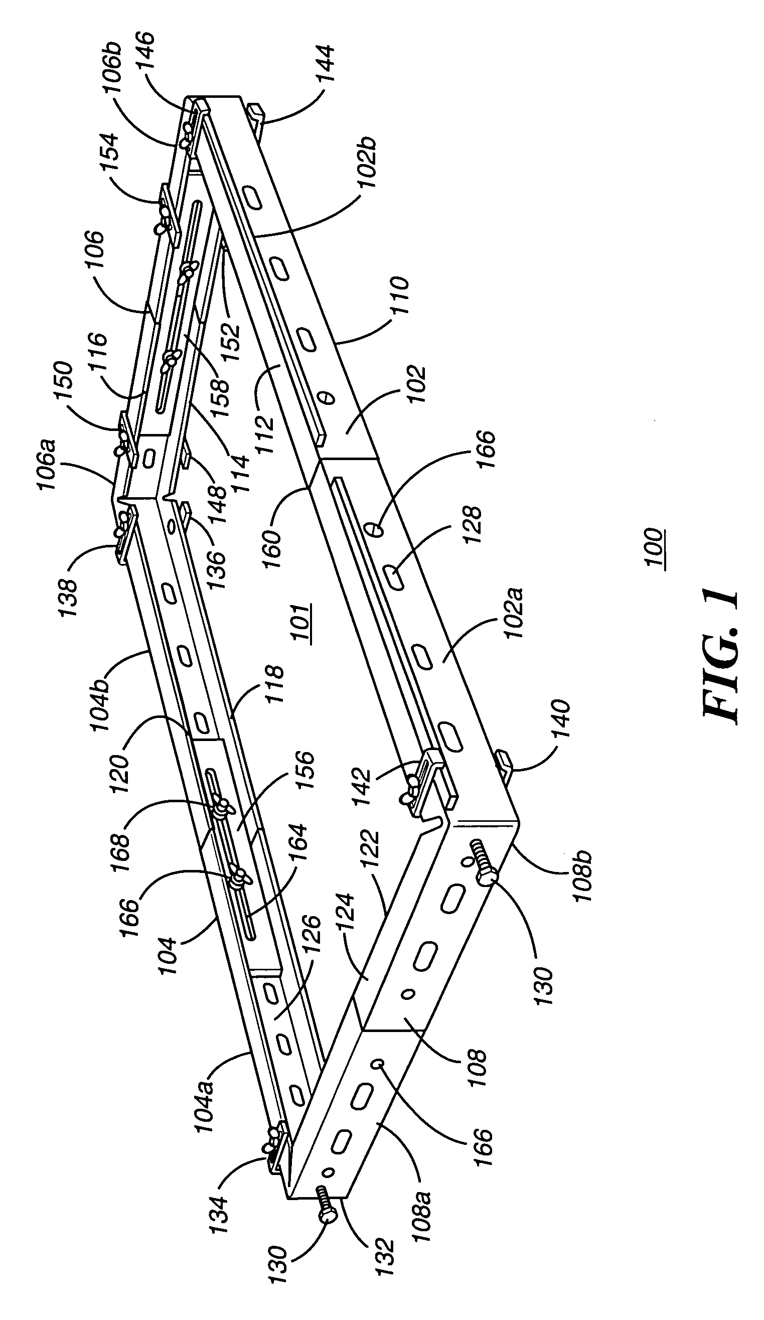
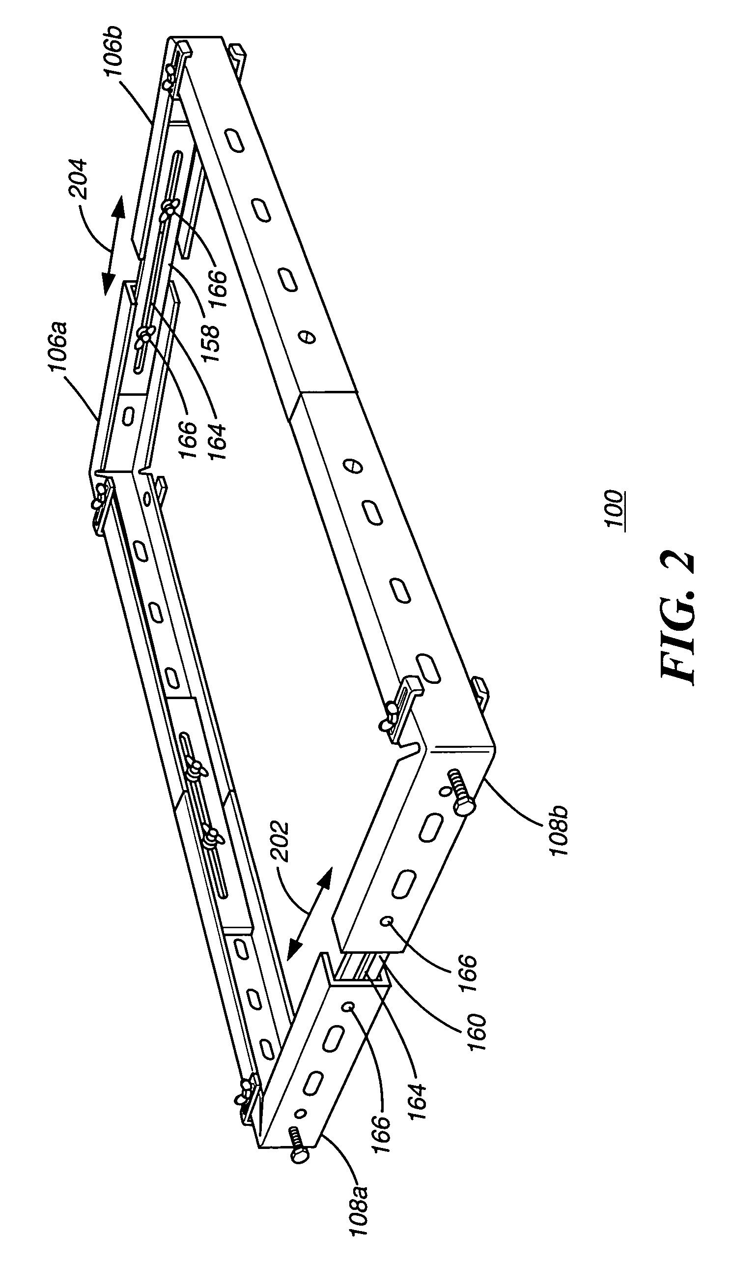
[0032]Described now is an exemplary door installation device according to an exemplary embodiment of the present invention. Referring to FIG. 1, a door installation device 100 is shown in a horizontal position. The door installation device 100 includes a first side element 102, a second side element 104, a top element 106, and a bottom element 108. The elements 102, 104, 106, and 108 are attached to each other in a rectangular arrangement, where each element meets the other at a 90-degree angle. The elements 102, 104, 106, and 108 each have inwardly disposed wall elements 110, 112, 114, 116, 118, 120, 122, and 124. The sets of inwardly disposed wall elements 110&112...


PUM

PropertyMeasurementUnit
sizeaaaaaaaaaa
height dimensionaaaaaaaaaa
width dimensionaaaaaaaaaa

Abstract

A device having a first, a second, a third, and a fourth slidably adjustable element arranged in a rectangular configuration, forming a rectangular pass-through opening approximately the size of a doorway and being slidably adjustable in a height dimension and a width dimension of the rectangle and having clamps for attaching the device to a doorframe so that the doorframe can be placed within a rough opening in a wall of a building while keeping a rectangular shape. The device has telescoping feet for adjusting the height off of the floor and leveling the frame. Once the frame is attached to the rough opening in the wall the clamps are released from the frame and the elements are contracted to allow the device to be removed from the frame, leaving the frame secured and properly aligned within the rough opening.

Description

BACKGROUND OF THE INVENTION[0001]1. Field of the Invention[0002]This invention relates in general to installing pre-hung doors and more particularly, to a device that properly aligns and shapes a pre-hung doorframe during installation within a rough opening in a wall.[0003]2. Description of the Related Art[0004]In building construction, in which doors are to be installed, the building contractors leave rough openings in the walls where finish carpenters, according to the architectural plans for the building, will later install the doorframes and doors. Doorframes generally consist of a head jamb spanning the distance between two side jambs and must be installed so that the jambs are completely plumb, or vertical, the head jamb is horizontal, the entire frame is square, and all parts of the frame are in the same plane. The jambs are secured in place with nails or screws to studs forming the rough opening in the wall. Once the frame is secured to the rough opening, a door or set of do...

Claims


Application Information

Patent Timeline
Patent Type & Authority Patents(United States)
IPC IPC(8): B25B27/14E04F21/00
CPCE04F21/0007Y10T29/53978Y10T29/53961Y10T29/49998E04F21/0015
Inventor MEDINA, JOSESMALLING, JASON M.
Owner WIDGET TOOLS
Why Eureka
Try Eureka