High capacity shear mechanism

a high-capacity, shear mechanism technology, applied in the direction of draw-gear, railway components, railway coupling accessories, etc., can solve the problems of high repair cost and premature failure of prior-art emergency release mechanisms, and reduce the number of premature failures , the effect of reducing the amount of fatigu

Inactive Publication Date: 2006-01-03
WESTINGHOUSE AIR BRAKE TECH CORP
View PDF7 Cites 7 Cited by
  • Summary
  • Abstract
  • Description
  • Claims
  • Application Information

AI Technical Summary

Benefits of technology

[0009]It is, therefore, one of the primary objects of the present invention to provide an emergency release mechanism which reduces the number of premature failures of emergency release mechanisms.
[0010]Another object, of the present invention, is to provide an emergency release mechanism which lessens the amount of fatigue in the emergency release mechanism during normal operation of the drawbar.

Problems solved by technology

Prior art emergency release mechanisms, such as the shear bolts shown in U.S. Pat. No. 6,499,613 to Grau et al., are subject to premature failure.
These premature failures can be expensive to repair and can cause inconvenience.

Method used


Image

  • High capacity shear mechanism
  • High capacity shear mechanism

Examples


Embodiment Construction

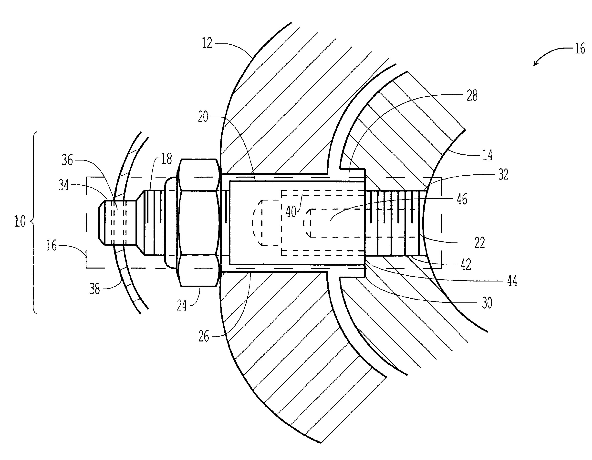
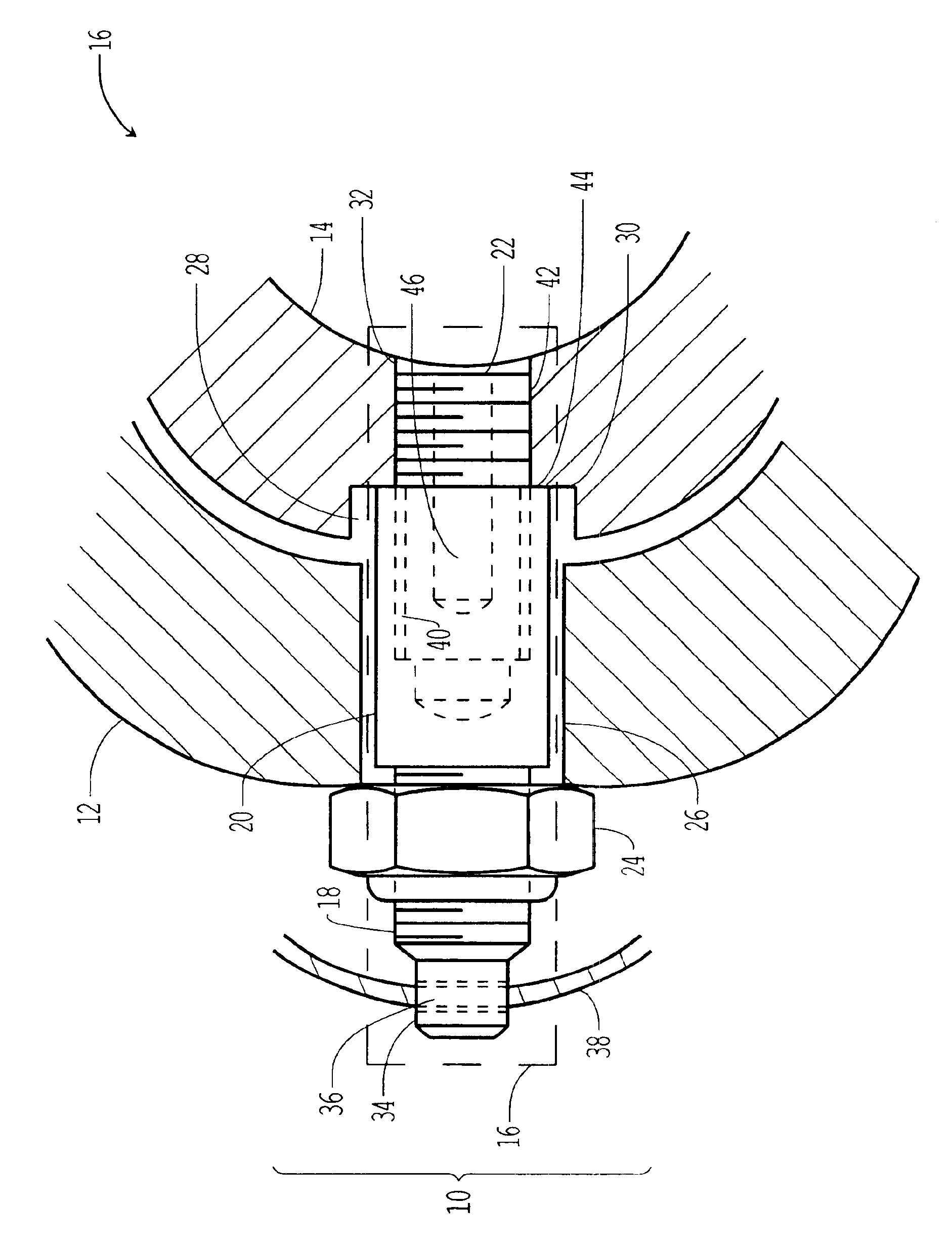
[0014]Turning now to the drawing, the sole FIGURE shows an emergency release mechanism 10 together with a drawbar body 12 and a release rail 14 and are shown generally as 16. The emergency release mechanism 10, in the preferred embodiment, consists of a fastener stud such as a two sided threaded stud 16, having a first threaded end 18, a cylindrical body 20 and a second threaded end 22, together with a fastener such as a lock nut 24, a through hole 26 in the drawbar body 12, a recess 28 having a machined surface 30 in the release rail 14, an aperture such as a tapped opening such as a threaded hole 32 in the release rail 14, the rim of which is located in the recess 28, and a chamfered dowel extension 34 of the first threaded end 18 having a hole 36 there through. A retaining wire 38 passes through the hole 36.

[0015]The dowel extension 34 is flattened such that a wrench interface is formed so that a wrench can be used on the dowel extension 34 to screw the second threaded end 22 sec...


PUM


Abstract

An emergency release mechanism for a railway drawbar, which reduces stress in two piece machine bolts inserts in emergency release mechanisms, includes a two sided threaded stud which screws into a release rail using one of the threaded stud ends, passes through a drawbar body, and is secured to the drawbar body by a nut screwed onto the other threaded stud end.

Description

CROSS-REFERENCE TO RELATED APPLICATIONS[0001]This application claims the benefit of U.S. Provisional Application No. 60 / 493,754, filed Aug. 8, 2003, and which is incorporated herein by reference.BACKGROUND OF THE INVENTION[0002]1. Field of the Invention[0003]This invention relates to railway drawbars and, more specifically, to shear mechanisms for railway drawbars.[0004]2. Description of Related Art[0005]Prior art emergency release mechanisms, such as the shear bolts shown in U.S. Pat. No. 6,499,613 to Grau et al., are subject to premature failure. These premature failures can be expensive to repair and can cause inconvenience.[0006]Therefore, it can be appreciated that an emergency release mechanism which lessens the number of premature failures of emergency release mechanisms is desirable.BRIEF SUMMARY OF THE INVENTION[0007]In one aspect the present invention generally provides an emergency release mechanism for a railway drawbar having a fastener stud, the fastener stud passing t...

Claims


Application Information

Patent Timeline
Patent Type & Authority Patents(United States)
IPC IPC(8): B61G1/00B61G7/14
CPCB61G7/14
Inventor GRAU, CURTISS A.SOMMERFELD, HOWARD R.
Owner WESTINGHOUSE AIR BRAKE TECH CORP
Why Eureka
Try Eureka