Dental implant and head for a compaction drill

a technology of dental implants and drills, which is applied in the field of dental implants and drill heads, can solve the problems of inconvenience and expense of extra surgery, metal portion of implants exposed above the gum line, and disadvantages of aesthetics, and achieves the advantages of stress dispersion, strong and tight bonding effect, and convenient us

Inactive Publication Date: 2006-01-03
CHOI YOUNG WOOK +4
View PDF15 Cites 56 Cited by
  • Summary
  • Abstract
  • Description
  • Claims
  • Application Information

AI Technical Summary

Benefits of technology

[0024]Considering the above-mentioned problems and disadvantages, it is one object of the present invention to provide a dental implant comprising a fixture and an abutment integrally formed with the fixture to accomplish simple implantation, good bone-to-fixture bonding and immediate mounting of an artificial crown thereon.
[0025]It is another object of the present invention to provide a dental implant having an improved structure in order to enhance initial reaction for curing of the bone and to efficiently spread the stress generated during chewing through the simple implantation of implant into the jawbone and the superior bonding between the fixture of the implant and the bone tissue.
[0026]It a still another object of the present invention to provide a dental implant including a settling portion having improved structure so as to prevent osteolysis of the cortex bone and maintain the original level of the alveolar bone after hard chewing.

Problems solved by technology

Currently, those varieties requiring only one surgery have the aesthetic disadvantage that the metal portion of the implant is exposed above the gum line.
This disadvantage does not apply in the case of those varieties requiring two surgeries, however, the inconvenience and expense of an extra surgery are disadvantages in themselves.
However, the above dental implants, currently in wide use, suffer from the disadvantage of using separate parts that are combined into a single artificial tooth.
The disadvantages of this two-step process are obvious.
Although some success has been reported with new designs that allow for connecting the abutment during the first surgery, the connection process remains cumbersome and time-consuming.
Also, there is a problem with the upper flange portion of the fixture where it comes in contact with the cortex bone.
The process of attaching a fixture to the jawbone using a single screw with a single thread is not easy.
This technique also reduces the life of the implant because it leaves the jawbone subjected to heat.
Also, it currently takes approximately 3 to 6 months for the bone to bond sufficiently with the implant to allow for the mounting of an artificial crown on the machined surface.
Operations mounting an artificial crown immediately after the implanting of a fixture have succeeded in non-tooth jawbone, however, the restriction remains that the quality and quantity of remaining bone must be sufficient to facilitate this technique.
Also, implants connecting a fixture, an abutment and an artificial crown with a threaded connection suffer from slack in the structure as well as screw scraps created when the screw is tightened.
This problem of slack remains unsolved, though the proper application of force when tightening the screw will minimize the problem and the development of a design that wedges the negative thread of the fixture against the positive thread of the abutment has also decreased this negative effect.
This can cause inflammation around the gums.
In this latter case the bond is relatively weak and insecure.
Also, because the thread portion of the fixture uses a single thread with a pitch of about 0.6 mm on the surface of a lathe-treated cylinder, it is relatively likely to fail or “strip” in the soft bone because of a limited surface area and the resulting concentration of stress in this small area of bone.
However, the problem of limited surface area and stress distribution around the screw remain essential design flaws in the present art.
This extraction of bone material is known to slow the bonding process.
However, due to recent advances, fixtures are now self-tapping, cutting down on the length of the procedure.
The new problem created by this self-tapping process is that the loose trabecular bone impedes the bonding process.
The use of dental mucous resin, with blood shedding, makes the operation complicated and more time-consuming.

Method used


Image

  • Dental implant and head for a compaction drill
  • Dental implant and head for a compaction drill
  • Dental implant and head for a compaction drill

Examples


Embodiment Construction

[0062]Hereinafter, various embodiments of the present invention will be explained in more detail with reference to the accompanying figures, however, it is understood that the present invention should not be limited to the following preferred embodiments set forth herein.

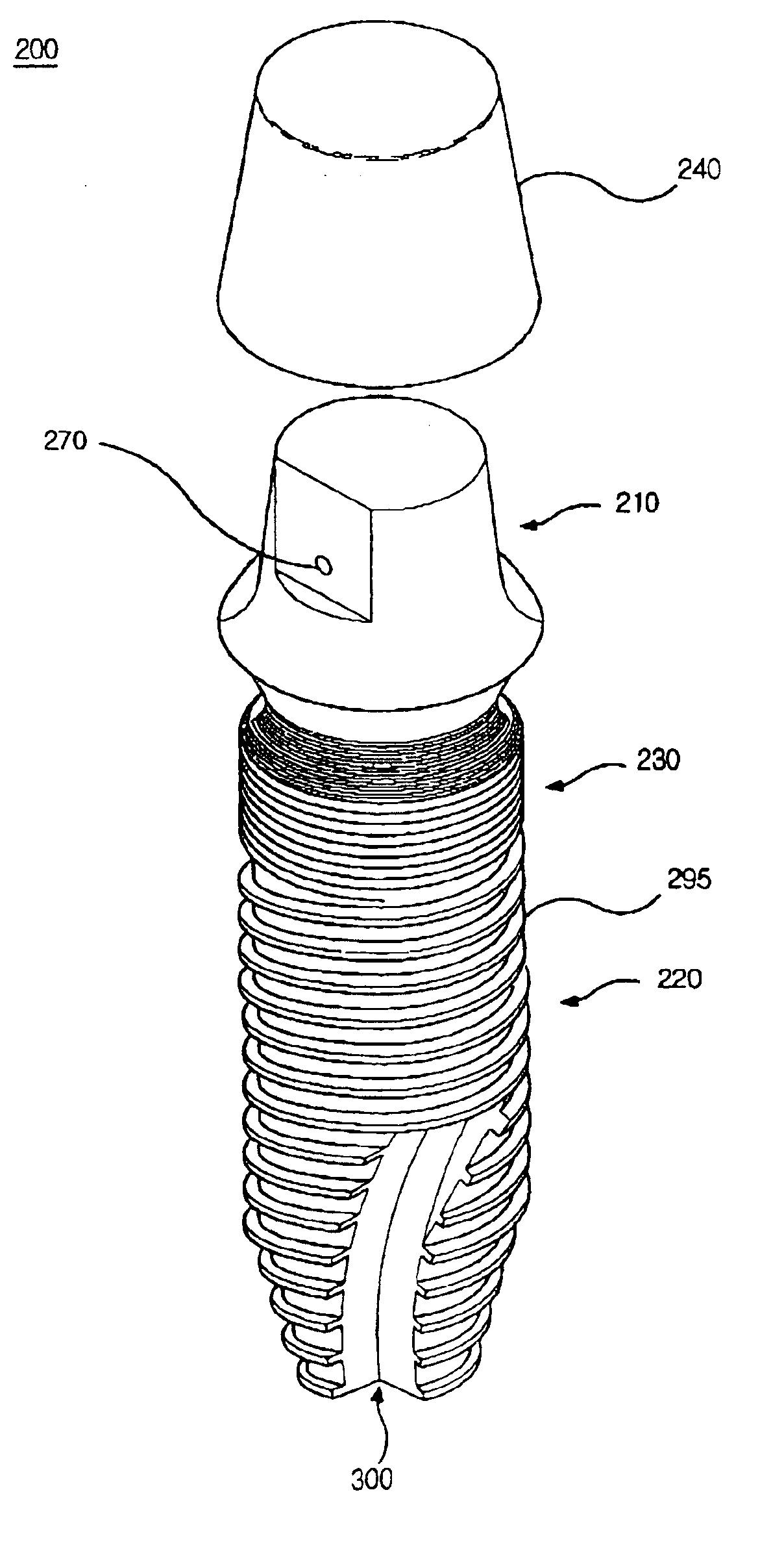
[0063]FIG. 5 is a perspective view for showing a dental implant according to one embodiment of the present invention and FIG. 6 is an enlarged side view for illustrating the dental implant in FIG. 5.

[0064]Referring to FIGS. 5 and 6, a dental implant 200 according to the present embodiment includes an upper abutment portion 210, a lower fixture portion 220 and a settling portion 230 formed between the abutment portion 210 and the fixture portion 220. Those portions 210, 220 and 230 are integrally formed. A crown cap 240 is mounted on the abutment portion 210 and adapted as the artificial crown.

[0065]The surface of the abutment portion 210 is generally machined. The surfaces of the fixture and the settling portions 22...


PUM


Abstract

A dental implant includes a fixture and an abutment in a body, and a head for a compaction drill is configured for implanting such an implant. The implant includes an upper abutment portion on which a denture is fixed, a fixture portion implanted in the jawbone and forming single or double threads, and a settling portion formed between the abutment portion and the fixture portion. The invention improves the stability of the implant, improves stabilization of the bone tissue affixed to the implant, effectively seals the socket from its surroundings and facilitates bonding between implant and jawbone. This is achieved because of the early healing of tissue around the implant and the greater surface area in contact with surrounding tissue. As a result, an artificial crown may be coupled with the implant during the same surgery.

Description

TECHNICAL FIELD[0001]The present invention relates to a dental implant and a head for a compaction drill, and more particularly to a dental implant that can immediately brace artificial dental structures thereon after the implant is placed because the implant includes a fixture and an abutment in a body can be easily implanted in a jawbone by an improved structure of the fixture, and also can accomplish enhanced bonding between a bone tissue and the implant. The present invention also relates to a head for a compaction drill specially designed for the implant.BACKGROUND ART[0002]In general, a dental implant is used as an artificial root composed of a metal having the shape of the crown root implanted in the jawbone where teeth are totally or partially lost so as to form artificial crowns on the artificial root after the artificial root combined with the jawbone. Such dental implants are available in varieties requiring two separate surgeries as well as varieties requiring only one.[...

Claims


Application Information

Patent Timeline
Patent Type & Authority Patents(United States)
IPC IPC(8): A61C8/00A61C13/00
CPCA61C8/0025A61C8/0022A61C13/00
Inventor CHOI, YOUNG-WOOKCHOI, YONG-CHANGKIM, SHIN-KOOKIM, HAN-GULEE, JAI-HYUN
Owner CHOI YOUNG WOOK
Why Eureka
Try Eureka