Electrical connector with improved locking means

a technology of locking means and electric connectors, applied in the direction of coupling device details, coupling device connections, contact members penetrating/cutting insulation/cable strands, etc., can solve the problems of low efficiency, low efficiency, and low efficiency of conventional wire nut connections, so as to improve the locking interconnection

Inactive Publication Date: 2006-01-03
CUTLER STEPHEN
View PDF13 Cites 32 Cited by
  • Summary
  • Abstract
  • Description
  • Claims
  • Application Information

AI Technical Summary

Benefits of technology

[0008]It is therefore an object of this invention to provide an electrical connector that provides for a significantly improved locking interconnection between segments of electrical wire or other type of electrical conductor.

Problems solved by technology

This procedure is usually tedious and time consuming, particularly for residential and business construction applications wherein a large number of connections are typically needed.
As a result, labor costs tend to be high.
Conventional wire nut connections also tend to be less than optimally secure.
Considerable time and effort may be required to locate and repair a defective connection.
However, the crimping process often destroys the connector and renders it ineffective.
It is usually quite difficult to perform the crimping process correctly.
Moreover, the crimp connector tends to pull apart from the wire fairly easily.
This type of electrical connection is often difficult to perform in the field.
This can result in failure of the wiring.
Additionally, known wire trap connectors are ineffective for use with stranded wire, which lacks the rigidity needed to open the spring clip.

Method used


Image

  • Electrical connector with improved locking means
  • Electrical connector with improved locking means
  • Electrical connector with improved locking means

Examples


Embodiment Construction

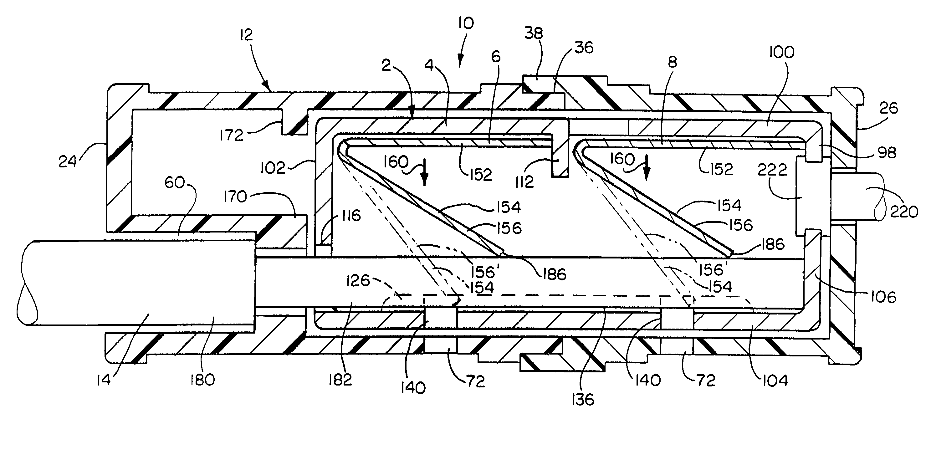
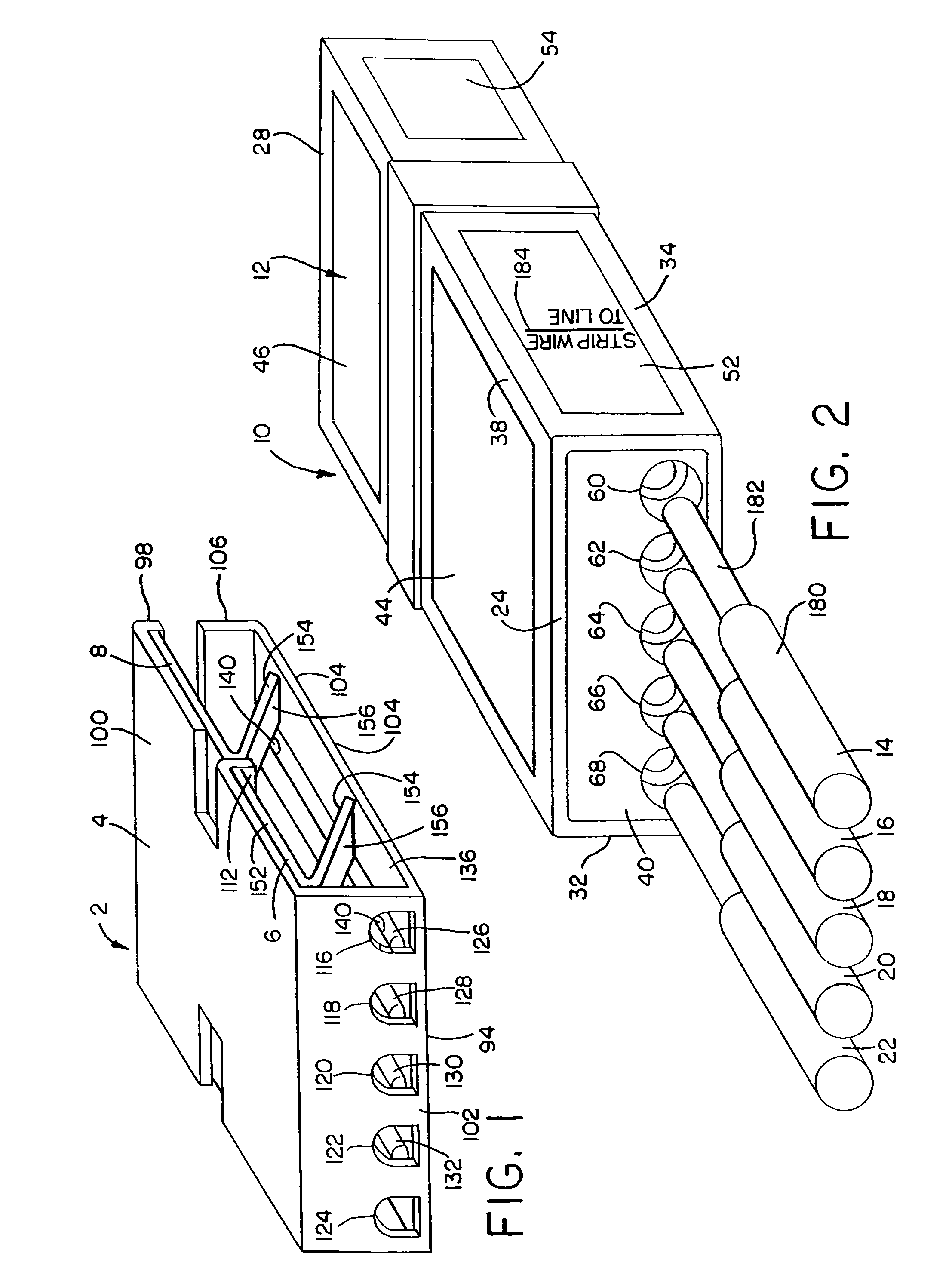
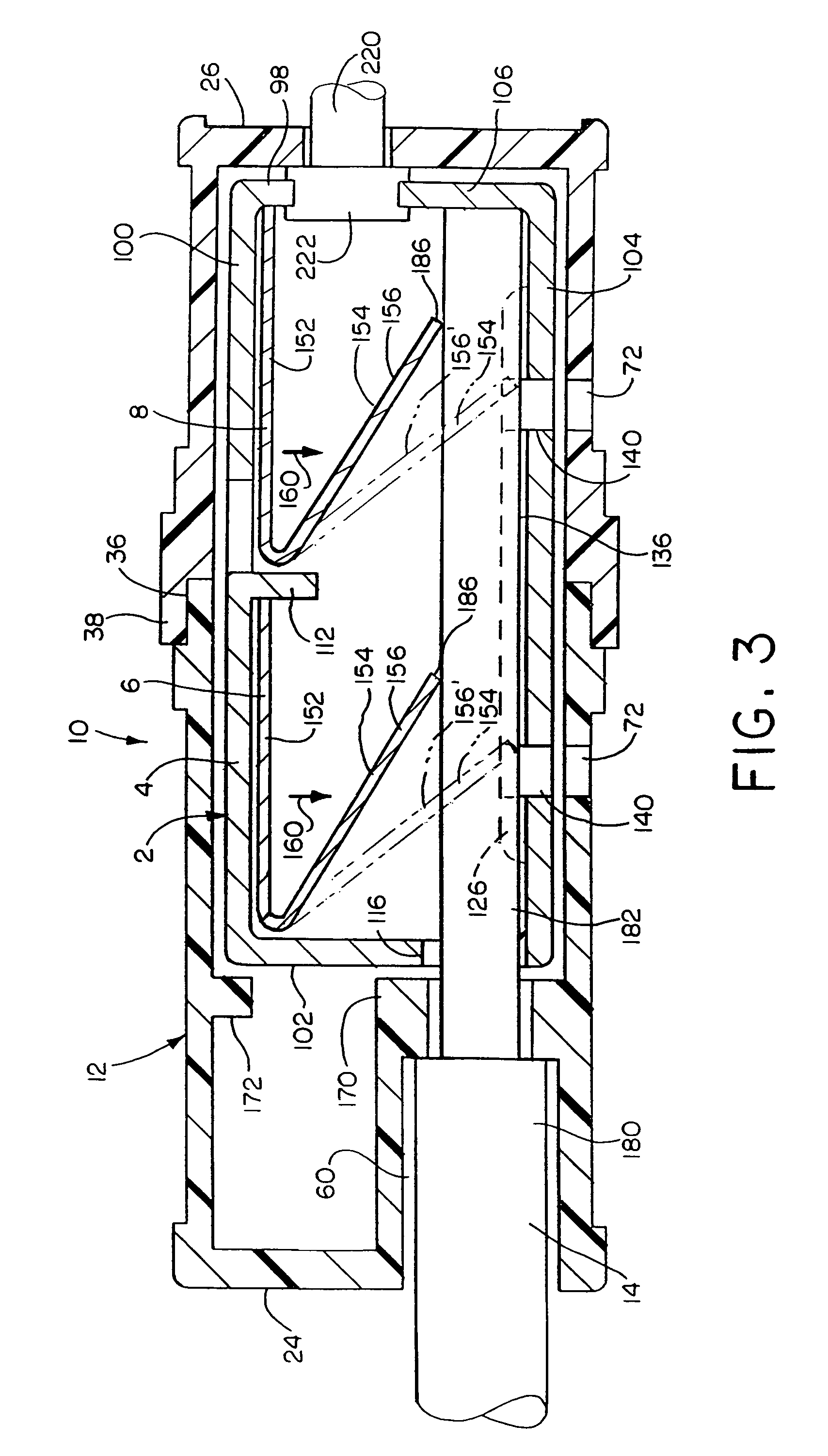
[0051]There is shown in FIG. 1 a preferred form of locking connector assembly 2 in accordance with this invention. The assembly features a conductive contact component 4 that carries a pair of serially arranged spring locking clip components 6 and 8. Assembly 2 may be used to accomplish a virtually limitless variety of electrical connections. The assembly may be carried within a plastic enclosure as described below, may be used without an enclosure and / or may be incorporated into various appliances, fixtures, switches, plugs and other items that require electrical connection.

[0052]There is shown in FIG. 2 a preferred electrical connector 10, which includes the locking connector assembly 2 mounted in a rectilinear enclosure 12 according to this invention. Connector 10 is designed for electrically and mechanically interconnecting a plurality of wires or other types of electrical conductors in a quick, secure and reliable manner. In the version shown in FIG. 2, five electrical wires 14...


PUM


Abstract

A locking connector is provided for electrically interconnecting first and second electrical conductors. The connector includes an enclosure that accommodates an electrical contact component electrically interengaged with the first conductor. At least two spring locking clips are mounted in the enclosure and serially arranged to face away from the inlet such that the clips are sequentially and resiliently opened by introducing the second conductor into the enclosure through the inlet. The clips are spring biased to grip the second conductor at a plurality of locations and hold the second conductor in electrical interengagement with the contact component. This enables the second conductor to resist disengagement from the contact component.

Description

RELATED APPLICATION[0001]The present application is a continuation of U.S. application Ser. No. 09 / 340,234, filed Jul. 1, 1999 now U.S. Pat. No. 6,257,919.FIELD OF THE INVENTION[0002]This invention relates to an electrical connector having a multiple spring locking mechanism.BACKGROUND OF THE INVENTION[0003]The standard wire nut is a common device currently available for electrically and mechanically interconnecting two or more segments of electrical wiring. First, the individual sections of wire are twisted together and then the nut is screwed onto the wire. This procedure is usually tedious and time consuming, particularly for residential and business construction applications wherein a large number of connections are typically needed. Effectively securing the nut to the wires usually requires practiced skill and experience. As a result, labor costs tend to be high. Conventional wire nut connections also tend to be less than optimally secure. Wires are apt to loosen and become dis...

Claims


Application Information

Patent Timeline
Patent Type & Authority Patents(United States)
IPC IPC(8): H01R4/24H01R4/48H01R13/629
CPCH01R4/4827H01R13/629Y10S439/91H01R4/48275
Inventor CUTLER, STEPHENVERWER, PAUL A.
Owner CUTLER STEPHEN
Why Eureka
Try Eureka