

Steam driven turbine generator system
a technology of steam turbines and generators, applied in the direction of electric generator control, liquid degasification, separation processes, etc., can solve problems such as steam pressure was
- Summary
- Abstract
- Description
- Claims
- Application Information
AI Technical Summary
Benefits of technology
Problems solved by technology
Method used
Image

Examples
Embodiment Construction
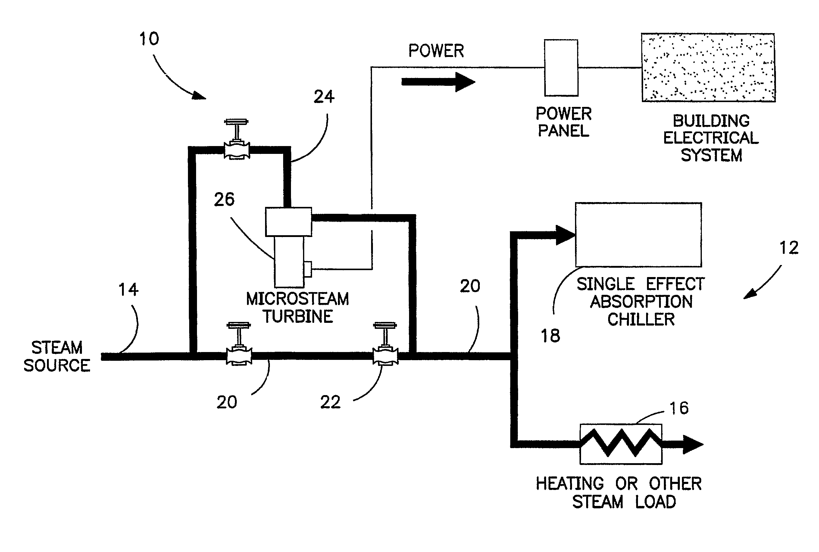
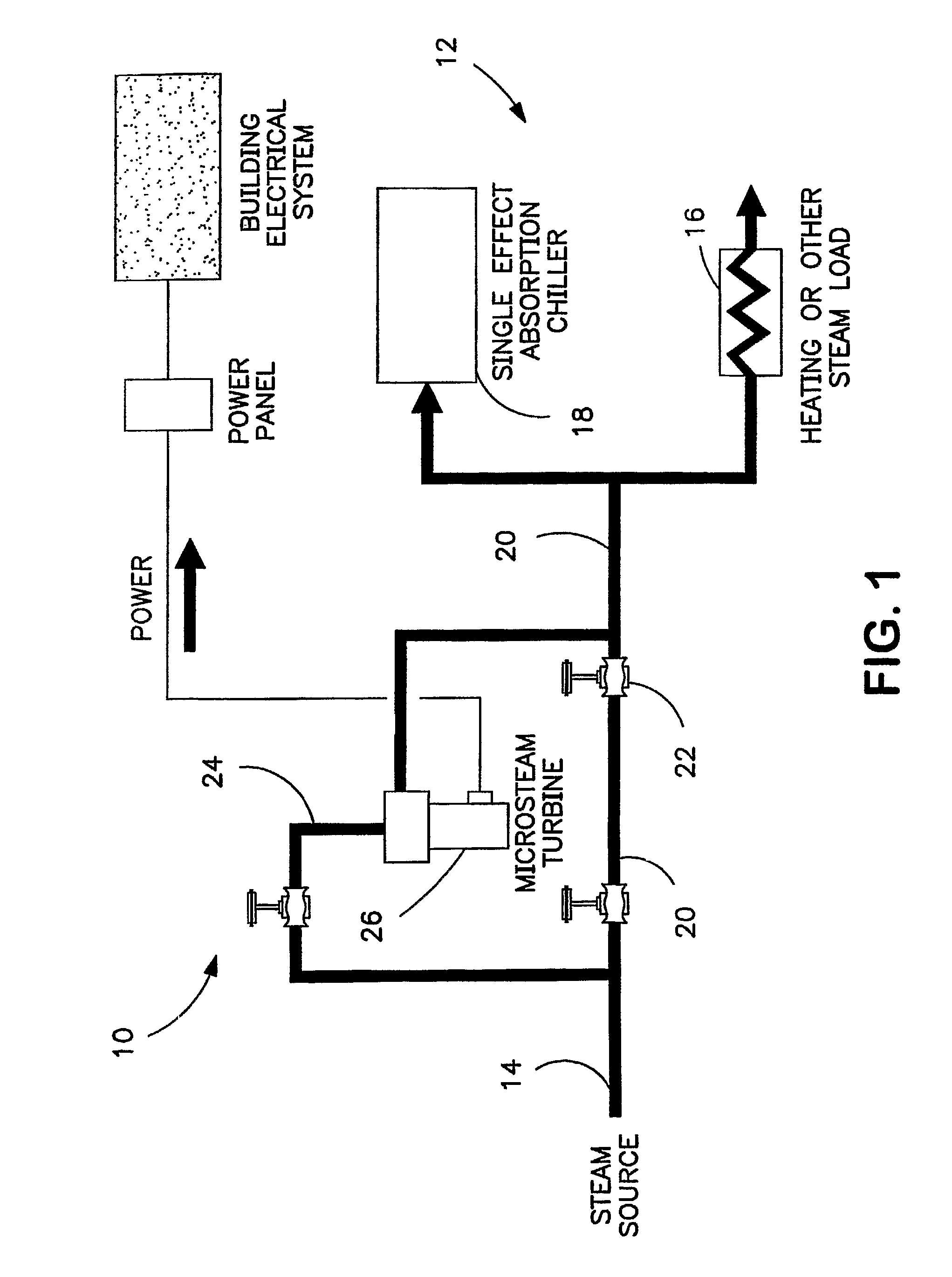
[0010]The invention relates to steam powered systems and, more particularly, to a system and method for converting excess steam power in such systems to use in generating electric power. This electric power can be used to power related or non-related systems, and results in practical use of such power rather than waste of the power through pressure reducing mechanisms previously used to reduce pressure from the steam source to the pressure required by a steam load.
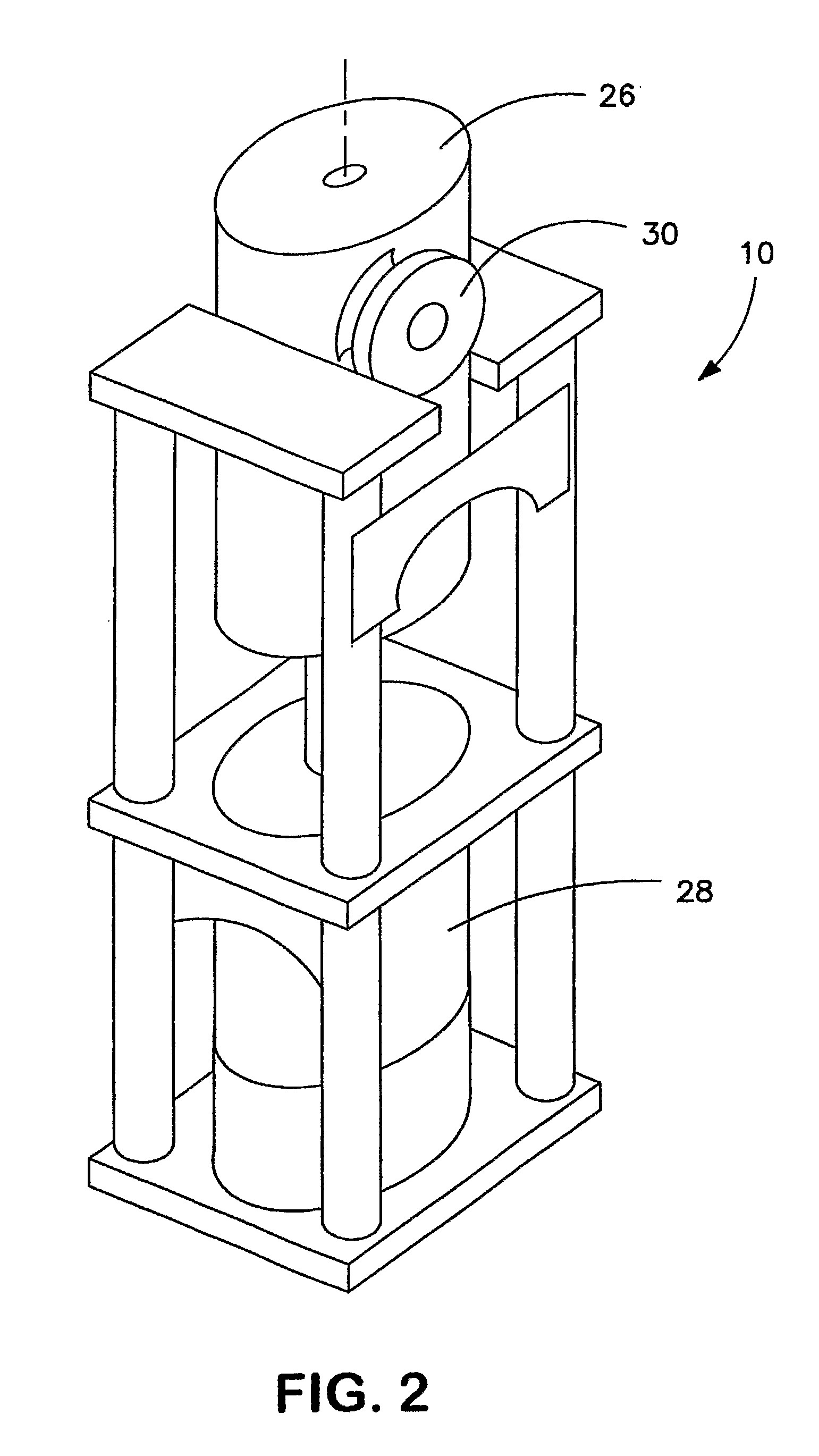
[0011]In the attached drawings, a schematic of the system is provided, and an advantageous vertical arrangement of components of the invention is also shown, whereby the system provides desirable use of excess steam power with a small footprint.
[0012]FIG. 1 schematically illustrates a system 10 in accordance with the invention, and includes a steam powered system 12 including a steam source 14, and one or more steam operated loads 16, 18, which are communicated through a line 20. Typically, steam can readily be provided at...
PUM
| Property | Measurement | Unit |
|---|---|---|
| pressure | aaaaa | aaaaa |
| pressure | aaaaa | aaaaa |
| pressure | aaaaa | aaaaa |
Abstract
Description
Claims
Application Information