Antenna tower and support structure therefor

a technology for supporting structures and antennas, applied in the field of antennas, can solve the problems of difficult to provide a compact structure, large typical antenna mast/tower, and difficult to maintain the compactness of the overall structure, and achieves the effects of reducing the risk of flexure and bending, and ensuring the stability of the overall structur

Inactive Publication Date: 2006-01-03
ANDREW LLC
View PDF3 Cites 19 Cited by
  • Summary
  • Abstract
  • Description
  • Claims
  • Application Information

AI Technical Summary

Benefits of technology

[0012]Briefly described, the present invention is an antenna tower and a support structure for use with an antenna tower, which allow a number of antennas or antenna panels to be mounted thereto, while maintaining the compactness of the overall structure and still providing high strength, such as is needed to resist high winds. In one preferred aspect, the invention preferably comprises an antenna tower including a mast. The antenna tower according to this preferred aspect of the invention also includes an antenna support structure mounted to the antenna mast for supporting one or more antennas or antenna panels. The antenna support structure includes a bottom element for mounting to the mast (or to another antenna support structure) and a top element spaced from the bottom element. A beam with multiple webs extends between the bottom element and the top element. The beam includes a central post and a number of stiffening webs extending generally radially outwardly from the central post. The stiffening webs help to provide substantially greater stiffness against flexure and bending, without making the overall structure larger (or not much larger effectively) or heavier. In this way, an antenna tower can be constructed that meets the competing needs of great structural rigidity, compactness, and light weight.

Problems solved by technology

Antennas and antenna towers are subjected to demanding environmental factors, such as high winds.
This has meant that the typical antenna mast / tower is large, bulky and generally unappealing in appearance.
Often, these antenna towers are obtrusive and contrast sharply with the surrounding environment in a negative way, and are commonly viewed by the community as “eye-sores.” This is due in part to the fact that most typical antenna towers have been constructed to provide functionality at the expense of form or aesthetics.
Unfortunately, the needs for high strength have tended to make it difficult to provide a compact structure.
This need for increased strength also tends to lead to larger structures, as mentioned above.
The present inventors, however, have found the low-strength module to be less than ideal in high wind applications or other high strength applications.
Unfortunately, known antenna tower designs generally do not provide the strength to support more than a limited number of antenna panels or external attachments, such as flags, banners, signage and the like, combined with an aesthetically pleasing compact appearance.
Further, they generally do not provide the strength needed to withstand harsh environmental stresses, in particular high wind, that are often encountered.

Method used


Image

  • Antenna tower and support structure therefor
  • Antenna tower and support structure therefor
  • Antenna tower and support structure therefor

Examples


Embodiment Construction

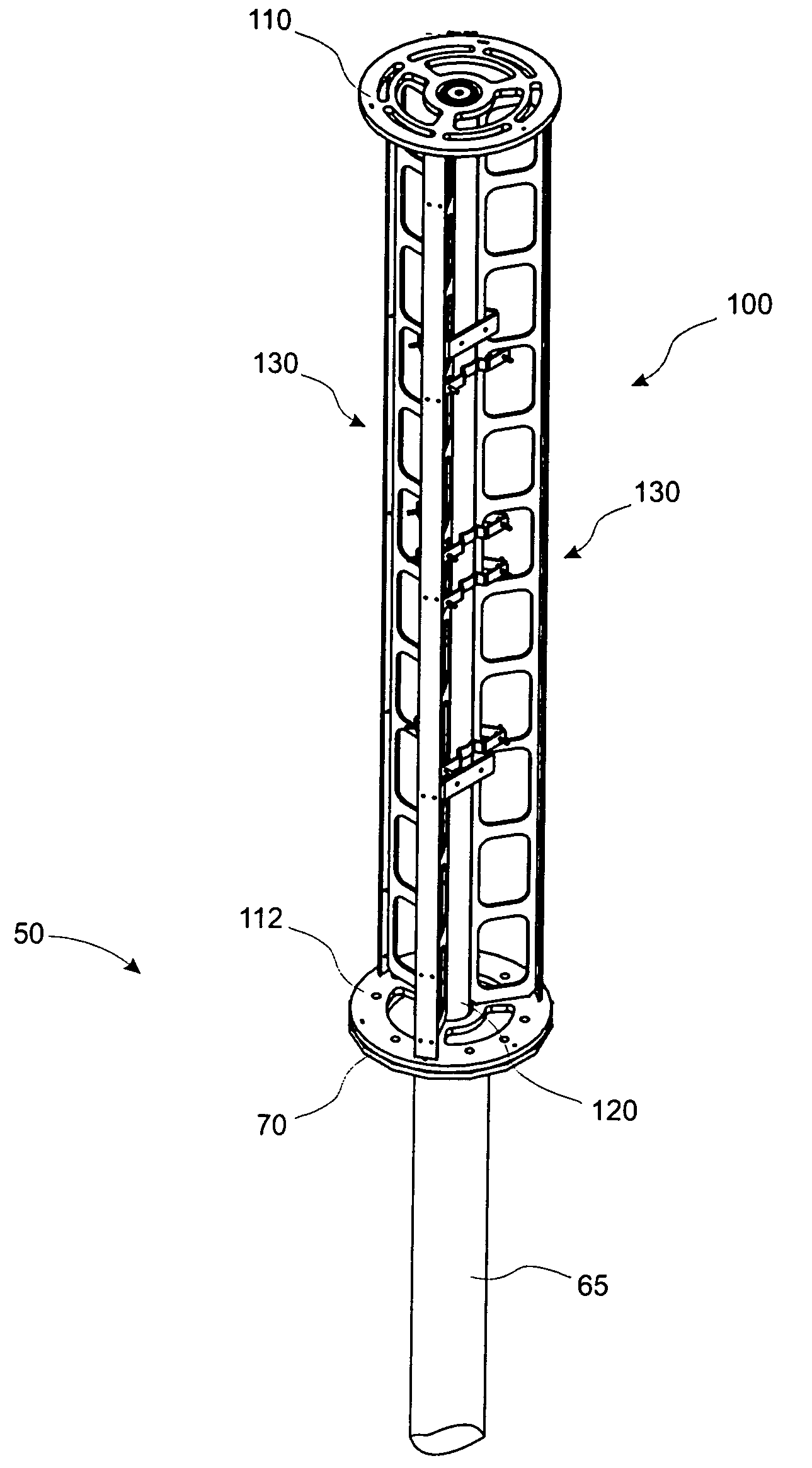
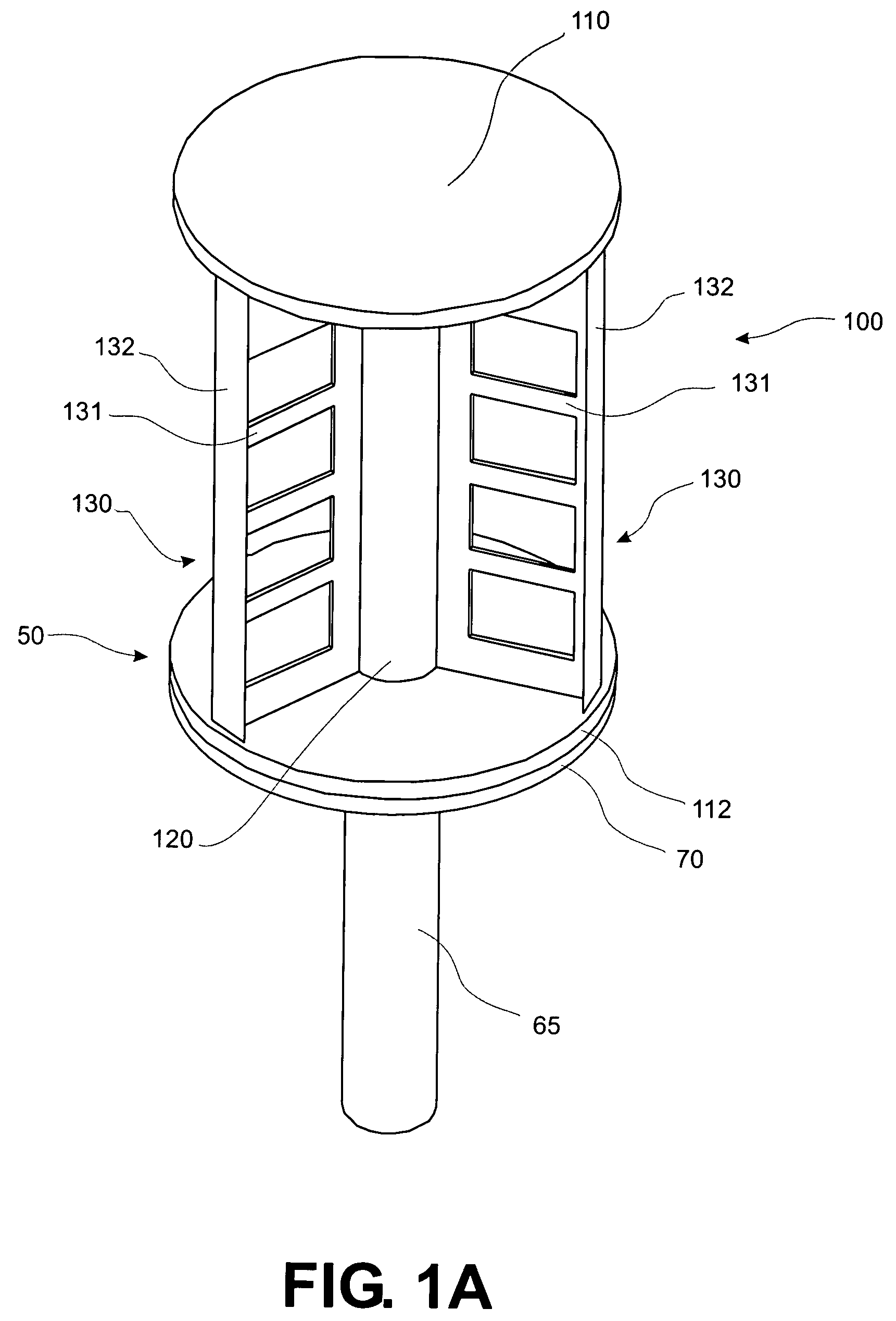
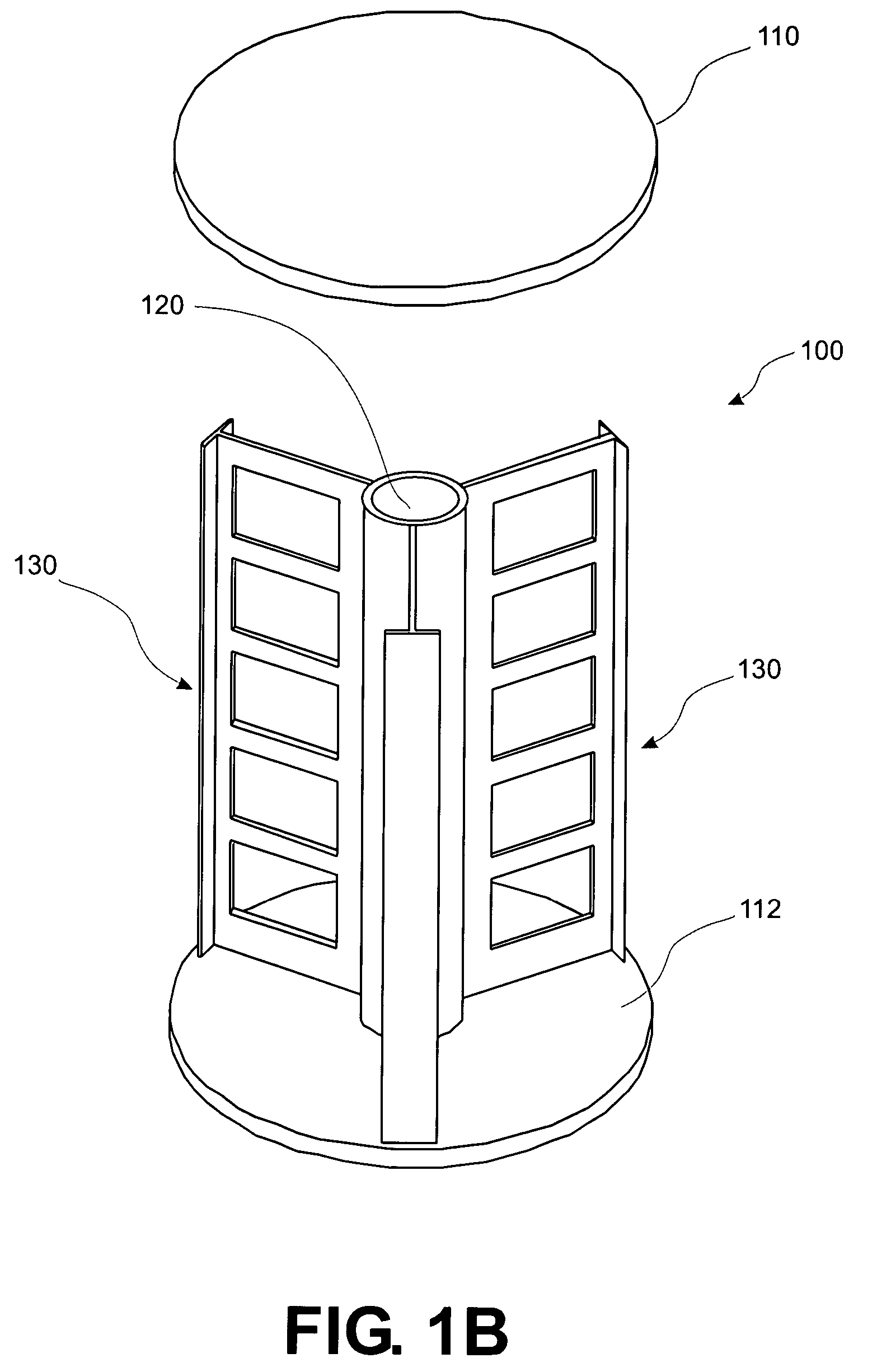
[0027]The present invention provides a compact antenna tower and support structure for use with an antenna tower that are capable of supporting multiple antenna panels. Towers and support structures according to the present invention are also capable of withstanding high winds. Moreover, because of the very good stiffness and strength obtained, the present invention allows the use of multiple support modules stacked on top of one or above another atop a tower mast, while still providing good resistance against excessive flexure from wind. Other modular structures, such as a support module for tower-mounted electronics, can be stacked between antenna support modules. It should be understood that the invention is not to be limited to the mounting of antennas or antenna panels, but instead could be used to mount a wide variety of components on a communications tower. The invention also allows the mounting of items not directly associated with wireless communications, such as a large fl...


PUM


Abstract

An antenna tower and support structure for use with an antenna tower, which allow a number of antennas or antenna panels to be mounted thereto, while maintaining the compactness of the overall structure and still providing high strength, such as is needed to resist high winds. The antenna tower includes an antenna support structure mounted to the antenna mast for supporting one or more antennas or antenna panels. The antenna support structure includes a bottom plate for mounting to the mast (or to another antenna support structure) and a top plate spaced from bottom plate. A beam with multiple webs extends between the bottom plate and the top plate. The beam includes a central post and a number of stiffening webs extending generally radially outwardly from the central post. The stiffening webs help to provide substantially greater stiffness against flexure and bending, without making the overall structure larger (or not much larger effectively). In this way, an antenna tower can be constructed that meets the competing needs of great structural rigidity and compactness.

Description

TECHNICAL FIELD[0001]The present invention relates generally to antennas and more particularly to an antenna tower and a support structure for mounting a wireless communications antenna on such a tower.BACKGROUND OF THE INVENTION[0002]Modern wireless communications systems, such as cellular or personal communication subscriber (PCS) telephone systems, are in wide use around the world. These systems generally include one or more antennas that are mounted on an associated antenna tower. Each antenna tower typically is associated with a base station.[0003]In order to provide wireless service to a given area (service area), wireless service providers normally erect one or more antenna towers at predetermined locations within the service area. As wireless communications services have become more popular, service providers have endeavored to build out wireless communications systems to provide service to larger areas. As a result, it has become common in many communities for there to be s...

Claims


Application Information

Patent Timeline
Patent Type & Authority Patents(United States)
IPC IPC(8): H01Q1/12
CPCH01Q1/1242
Inventor JANOSCHKA, DARIN M.BEAFORE, JOHN L.PEAVY, ANTHONY W.
Owner ANDREW LLC
Why Eureka
Try Eureka