Head-mounted projection display system

a projection display and projection display technology, applied in the field of head-mounted projection display systems, can solve the problems of limiting the applicability of special uses, complex systems, and high implementation costs, and achieve the effect of wide viewing angles

Inactive Publication Date: 2006-01-03
KONINKLIJKE PHILIPS ELECTRONICS NV
View PDF13 Cites 49 Cited by
  • Summary
  • Abstract
  • Description
  • Claims
  • Application Information

AI Technical Summary

Benefits of technology

[0010]The projected image is directed to a high-gain, retro-reflective viewing screen, which returns light from the low power projector(s) at sufficient brightness for the viewer to see the projected image(s). Due to the small angle of return (on the order of about 1–2 degrees), each eye sees only the image from its adjacent projector, enabling stereoscopic viewing in the event that separate images are projected by each projector, without the attenuation, temporal or optical manipulation common to known stereoscopic display systems.
[0011]The retro-reflective viewing screen is capable of having a wide viewing angle. This characteristic, together with the retro-reflectivity of the screen, permits a single viewer or multiple viewers, each with their own headgear, to see the same image or different images at large angles of view without significant degradation, making possible, for example, one or more viewers moving within the viewing space, or an audience of stationary viewers.

Problems solved by technology

As will be appreciated, this system is complex and would be expensive to implement, limiting its applicability to specialized uses such as military or commercial pilot training.

Method used


Image

  • Head-mounted projection display system
  • Head-mounted projection display system
  • Head-mounted projection display system

Examples


Embodiment Construction

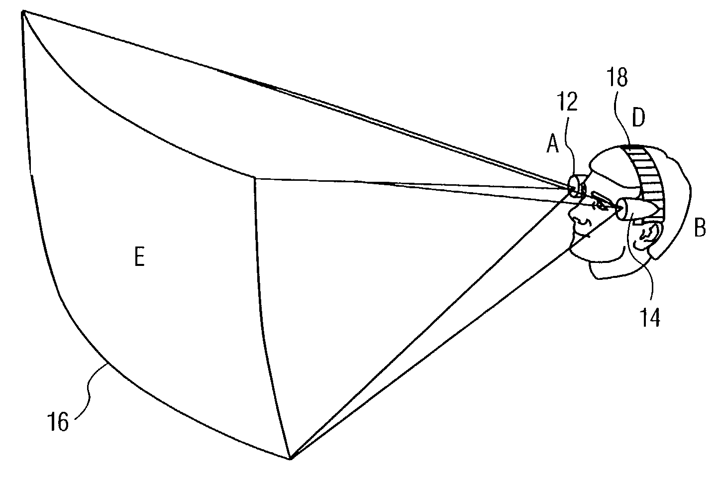
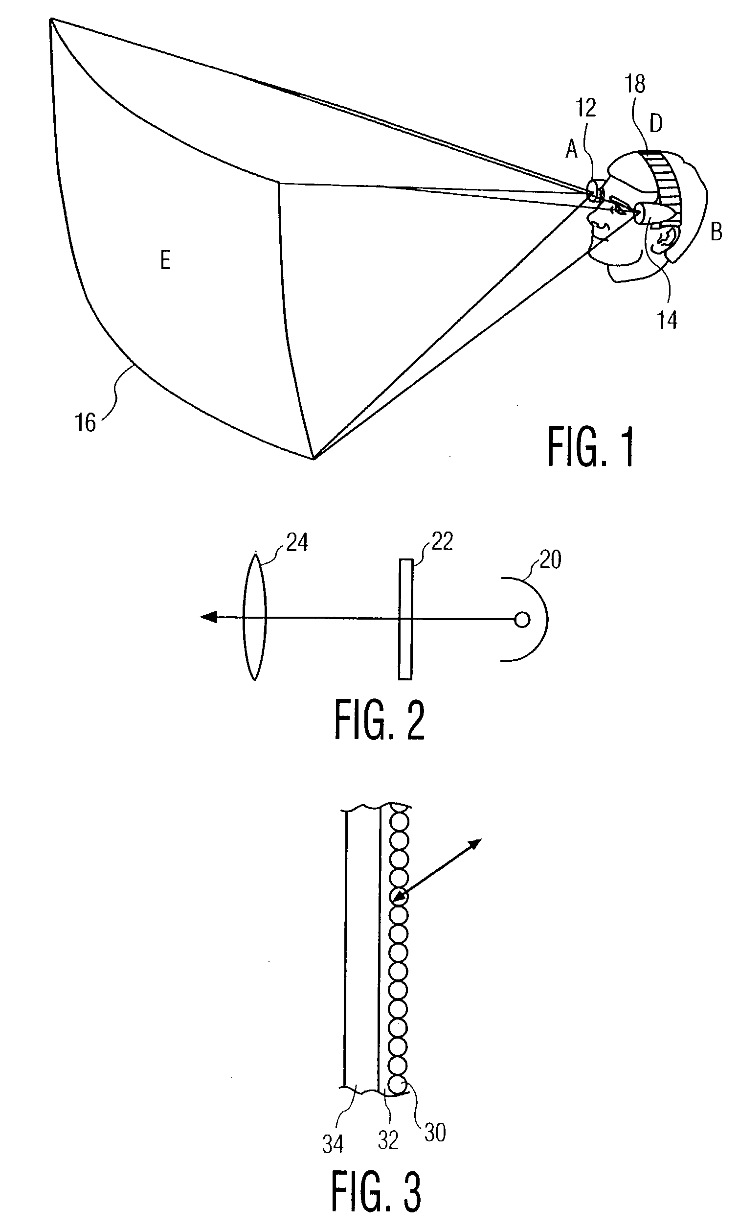
[0016]In FIG. 1, two low power projectors 12 and 14 are mounted on the viewer's head close to each eye. Each projector is aimed at the viewing screen 16 along the direction of the line of sight of the adjacent eye of the viewer. The projectors 12 and 14 are stabilized and referenced to the viewer's head by means of a headband 18. Possible alternative headgear include a hat or helmet.

[0017]The projectors each include a light source 20, an electro-optical light modulator 22, such as an LCD, and a projection lens 24, in the arrangement shown schematically in FIG. 2. Light may alternatively be supplied from a remote light source, eg., via optical fibers. Display information, such as video or computer generated display signals, are supplied to the modulator 22 via electrical cables, not shown.

[0018]The viewing screen 16 is retro-reflective. That is, it returns all incident light back to the source within a narrow angle (about 1–2 degrees). Consequently, regardless of changes in the angle...


PUM


Abstract

A head-mounted projection display system is characterized by a pair of head-mounted low-power image projectors mounted adjacent the eyes of the viewer, and aimed to project in a direction along the line of sight of the viewer toward a high-gain, retro-reflective screen. Stereoscopic viewing is enabled by projecting separate images to the right and left projectors. The retro-reflectivity of the screen ensures that the right and left images will be returned to the right and left eye, respectively.

Description

CROSS REFERENCE TO RELATED APPLICATIONS[0001]This is a continuation of application Ser. No. 09 / 206,436, filed Dec. 7, 1998 now U.S. Pat. No. 6,535,182.BACKGROUND OF THE INVENTION[0002]This invention relates to a head-mounted projection display system, and more particularly relates to such a display system in which the display is stereoscopic.[0003]A variety of head-mounted displays are in use or have been proposed. Usually they involve a CRT or a spatial light modulator coupled to a source of light to create the display image. In the simplest versions, the images are viewed directly by the eye, assisted by suitable optics. See, for example, Japanese Kokai 4-34588 (A). Some versions permit the ambient environment to be viewed through the apparatus while information is added to the observer's view from the display. See, for example, U.S. Pat. No. 5,677,795.[0004]In UK patent application GB 2 043 940 A, a ground-based craft-flight simulator is described, in which separate right and lef...

Claims


Application Information

Patent Timeline
Patent Type & Authority Patents(United States)
IPC IPC(8): G09G5/00G02B27/00G02B27/02G02B27/01G09B9/30H04N5/64H04N13/04
CPCG02B27/017G09B9/307G02B27/0172G02B2027/0132
Inventor STANTON, DOUGLAS A.
Owner KONINKLIJKE PHILIPS ELECTRONICS NV
Why Eureka
Try Eureka