
Sound absorptive protective mat

a technology of sound absorption and protective mats, applied in the direction of roofs, machines/engines, synthetic resin layered products, etc., can solve the problem of not acting like a conventional spring-mass system, and achieve the effect of superior acoustic properties

Inactive Publication Date: 2006-01-10
AUTONEUM MANAGEMENT AG
View PDF16 Cites 42 Cited by
  • Summary
  • Abstract
  • Description
  • Claims
  • Application Information

AI Technical Summary

Benefits of technology

The present invention aims to provide a thin and lightweight protective mat that has excellent sound insulation properties.

Problems solved by technology

The technical problem addressed in this patent is the need for a lighter and more effective automotive protective mat that can significantly reduce sound levels in the vehicle and also be used in residential and commercial structures to reduce echoing in rooms with hard floors. Current protective mats are heavy and poor sound absorbers, which can be compensated by an increased thickness of the backing layer.

Method used


Image

  • Sound absorptive protective mat
  • Sound absorptive protective mat

Examples


Embodiment Construction

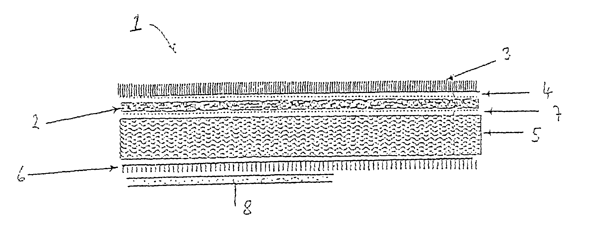
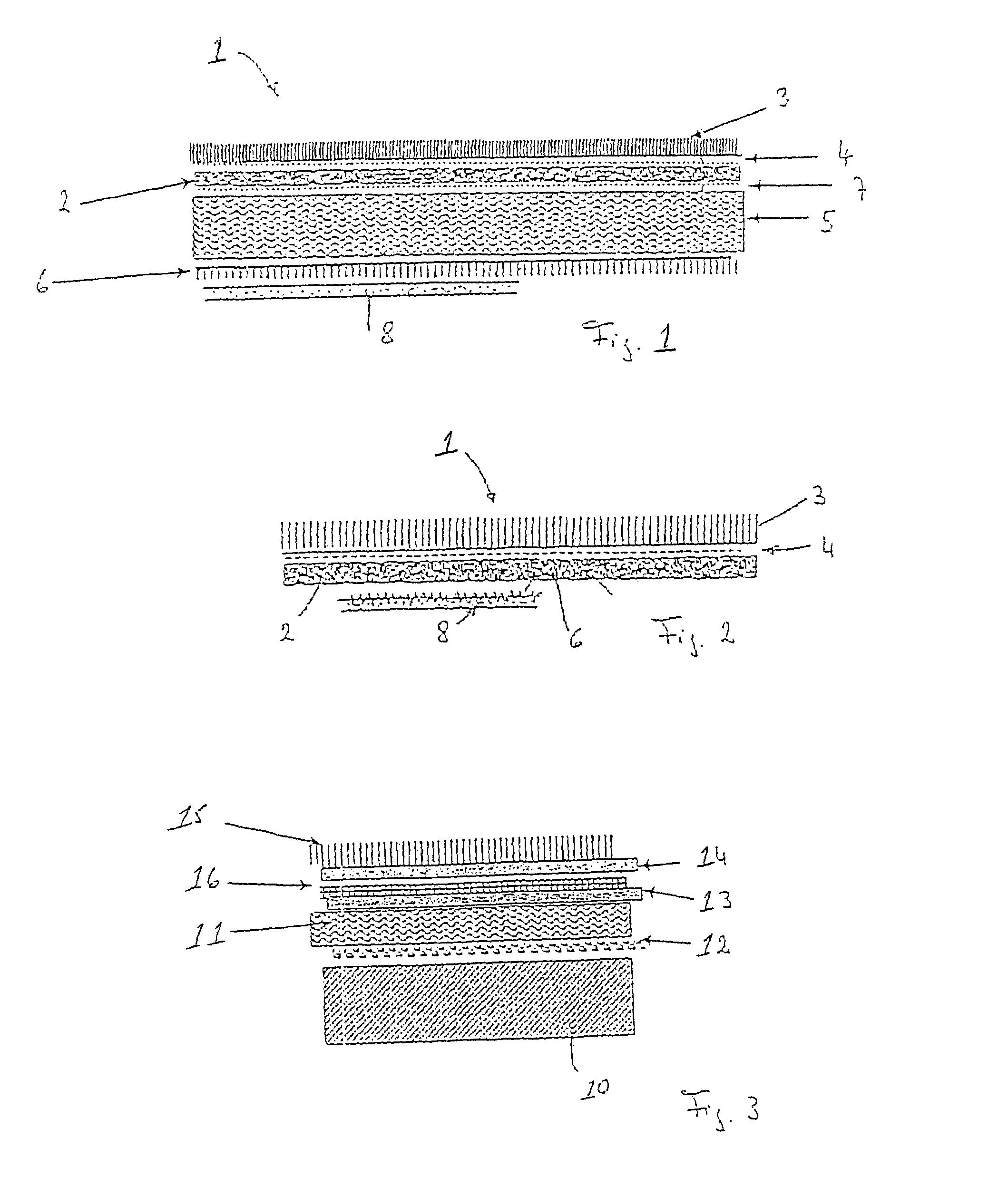
[0014]FIG. 1 shows a sectional view of a preferred embodiment of the sound absorptive protective mat 1 incorporating a decoupler 6 and comprising a hydrophobic and air flow resistant layer 2. This hydrophobic and air flow resistant layer 2 carries optionally a face fabric or carpet 3, which both are permeable to air, and are preferably bonded by an adhesive layer 4; the face fabric or carpet 3 can also be mechanically fixed to the hydrophobic and air flow resistant layer 2. The hydrophobic and air flow resistant layer 2 can be fibrous or made of TPE (elastomer), rubber or vinyl. Underneath this hydrophobic and air flow resistant layer 2 there is foreseen a high loft, low air flow resistance layer 5, comprising at its bottom an additional non-skid barrier layer functioning as a decoupler 6. This high loft, low air flow resistant layer 5 is preferably attached to the hydrophobic and air flow resistant layer 2 with the aid of a second adhesive layer 7.

[0015]The combination of the face ...


PUM

PropertyMeasurementUnit
Volumeaaaaaaaaaa
Volumeaaaaaaaaaa
Volumeaaaaaaaaaa

Abstract

The present invention concerns an automotive protective mat (1), also known as throw in mat or protective mat. This mat comprises a microporous stiffening layer (2) (acoustical membrane). This layer may be composed of several sheets. The overall air flow resistance is between 500 Ns/m3–4000 Ns/m3. It is essential for this mat (1) that it is hydrophobic. In order to achieve an enhanced acoustical effectiveness a decoupling layer (6) is foreseen between the microporous stiffening layer (2) and the vehicle floor (8). This decoupling layer might be incorporated in the mat (1) or constituted by the underlaying carpet or sound absorber of the vehicle floor. Further layers or sheets such as adhesive layers, non skid layers, face fabrics or carpets and/or loft layers can be added to the claimed mat.

Description


Claims


Application Information

Patent Timeline
Owner AUTONEUM MANAGEMENT AG
Learn More