Portable modular storage support device

a modular storage and support device technology, applied in the direction of suspension devices, cycle stands, cycle equipment, etc., can solve the problems of not being able to disclose the device in the known prior art, devices that require permanent installation, and may be impractical or undesirable, and achieve the effect of convenient assembly and portability

Inactive Publication Date: 2006-01-10
FICKETT GLENN A
View PDF59 Cites 81 Cited by
  • Summary
  • Abstract
  • Description
  • Claims
  • Application Information

AI Technical Summary

Benefits of technology

[0010]It is an object of this invention to provide a modular support structure which is easily assembled, portable, and does not demand permanent structure.

Problems solved by technology

However, most such storage devices require permanent installation which may be impractical or undesirable as in an hotel, apartment or condominium setting.
In addition, most such structures have a particular configuration which cannot be altered as an individual's needs change.
None of the known prior art disclose the device set forth herein.

Method used


Image

  • Portable modular storage support device
  • Portable modular storage support device
  • Portable modular storage support device

Examples


Embodiment Construction

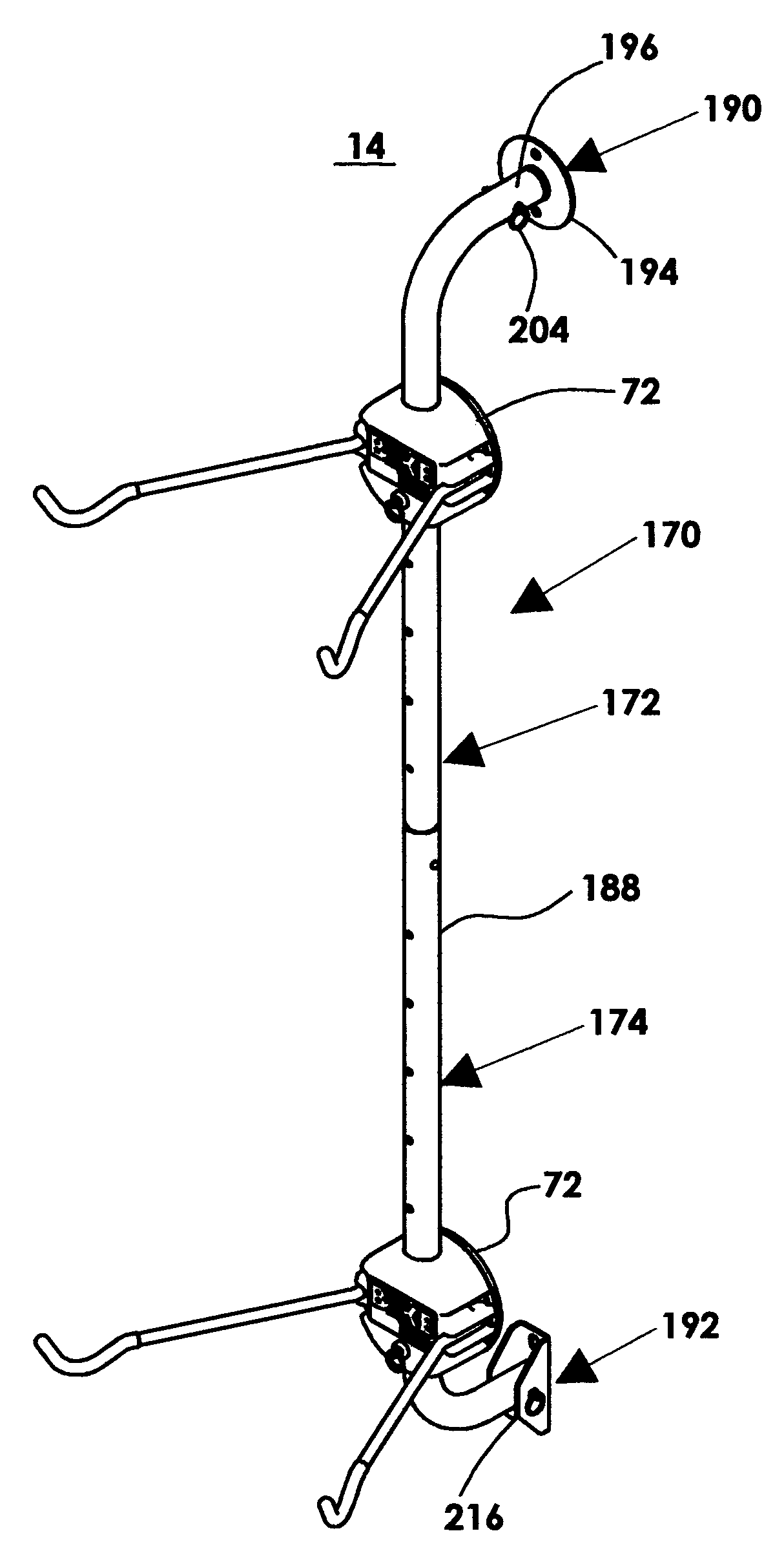
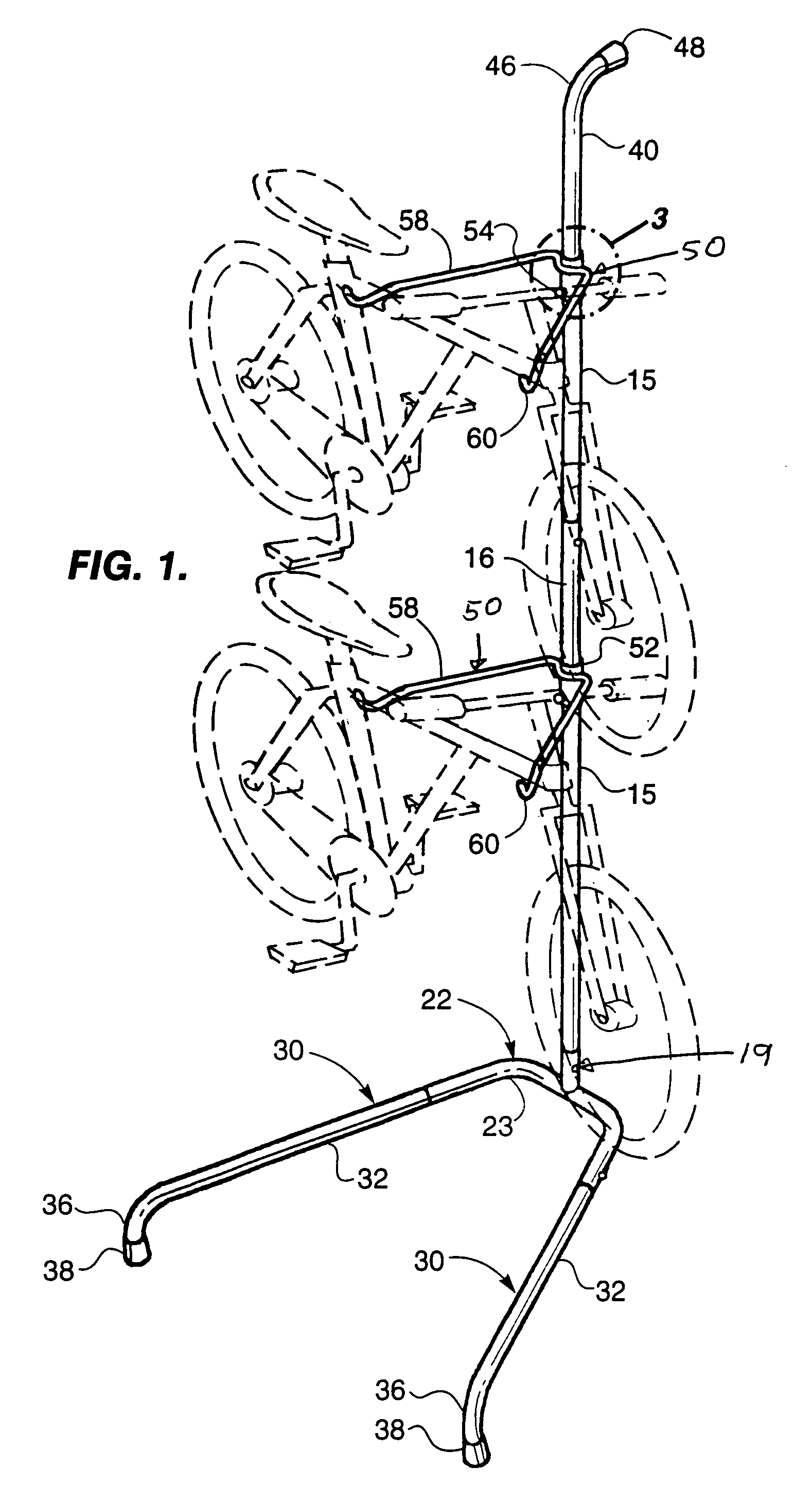
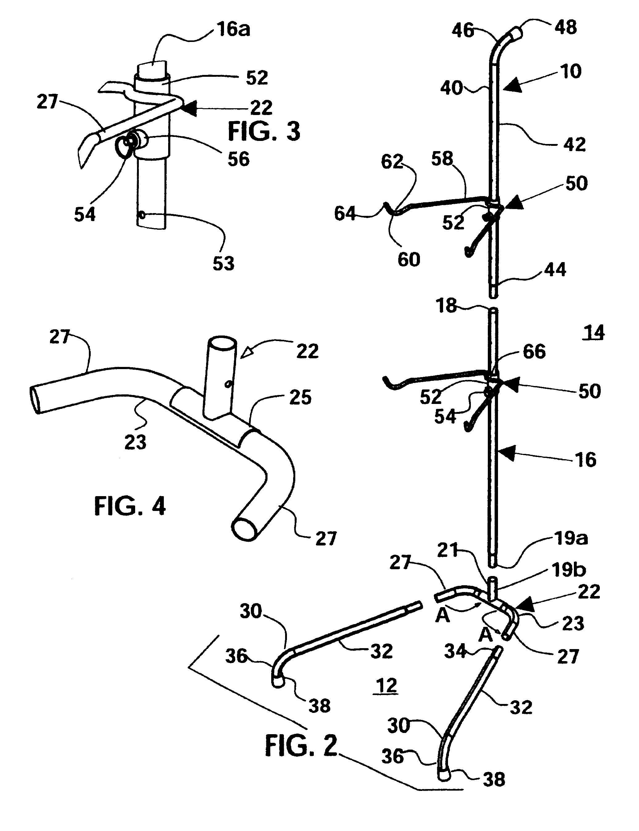
[0030]A modular storage support device 10 supports differing items suspended above a floor 12. Device 10 rests upon floor 12 and comprises a vertical member 16 extending upwardly which has an upper end 18 and a lower end 20. A base member 22 has a base vertical portion 21 which receives lower end 20 of vertical member 16 and a U-shaped portion 23 which is oriented perpendicular to vertical member 16. U-shaped portion 23 has two leg portions 27 extending laterally with respect to the sides thereof. Two L-shaped support legs 30 are received in a respective one of leg portions 27 and extend forward therefrom. A foot portion 36 extends downwardly from each L-shaped support leg 30 to rest upon floor 12. An L-shaped wall brace 40 is received within upper end 18 of vertical member 16 and extends upwardly and then rearwardly from vertical member 16 to engage a vertical wall 14. One or more supports 49 are slidably secured to vertical member 16 and upwardly extending section of L-shaped wall...


PUM


Abstract

A modular storage support device supports items suspended above a floor. The device rests upon the floor and comprises a vertical member extending upwardly which has an upper end and a lower end. A base member has a base vertical portion which receives the lower end of the vertical member and a U-shaped portion which is oriented perpendicular to the vertical member. The U-shaped portion has two leg portions extending laterally with respect to the sides thereof Two L-shaped support legs are received in one of the leg portions and extend forward therefrom. A foot portion extends downwardly from each of the L-shaped support legs to rest upon a floor. An L-shaped wall brace is received within the upper end of the vertical member and extends upwardly and then rearwardly from vertical member to engage a vertical wall. One or more supports are slidably secured to the vertical member and the upwardly extending section of the L-shaped wall brace. Each of the one or more supports have at least one support arm being mounted thereto. Each of the at least one support arms is parallel to, shorter than and positioned between the support legs and engages an item for support of said item.

Description

RELATED APPLICATION[0001]This is a continuation-in-part of patent application Ser. No. 10 / 043,420 filed Jan. 10, 2002, now U.S. Pat. No. 6,843,380 which is a continuation-in-part of patent application Ser. No. 09 / 653,834 filed Sep. 1, 2000, now abandoned, which is a continuation-in-part of design patent application Ser. No. 29 / 115,420 filed on Dec. 14, 1999, now U.S. Pat. No. D437,164.TECHNICAL FIELD[0002]This invention relates in general to a modular storage support device, and, and, more particularly, to a portable device having a modular format which is easily transported and assembled.BACKGROUND OF THE INVENTION[0003]Many individuals prefer to store items off the floor to minimize space requirements and the like. However, most such storage devices require permanent installation which may be impractical or undesirable as in an hotel, apartment or condominium setting. In addition, most such structures have a particular configuration which cannot be altered as an individual's needs...

Claims


Application Information

Patent Timeline
Patent Type & Authority Patents(United States)
IPC IPC(8): A47F7/00
CPCA47F5/04A47F5/08A47F7/00F16M11/00F16M11/22F16M13/02B62H3/12F16M2200/08
Inventor FICKETT, GLENN A.
Owner FICKETT GLENN A
Why Eureka
Try Eureka