While this embodiment was adequate for certain applications, as technology evolved to demanded higher dispensing accuracy, its application became somewhat limited.
Such conventional pump systems suffer from several limitations.
The motor and rotary
clutch mechanisms are bulky and heavy, and are therefore limited in application for modern dispensing applications requiring increasingly precise, efficient, and fast operation.
The
excessive weight limits use for those applications that require contact of the pump with the substrate, and limits
system speed and accuracy, attributed to the high g-forces required for quick movement of the
system.
The mechanical
clutch is difficult to control, and coasts to a stop when disengaged, resulting in deposit of excess fluid.
However, the spring adds to the length of the
cartridge, and contributes to system complexity.
This further limits
material flow and can contribute to material “balling” and clogging.
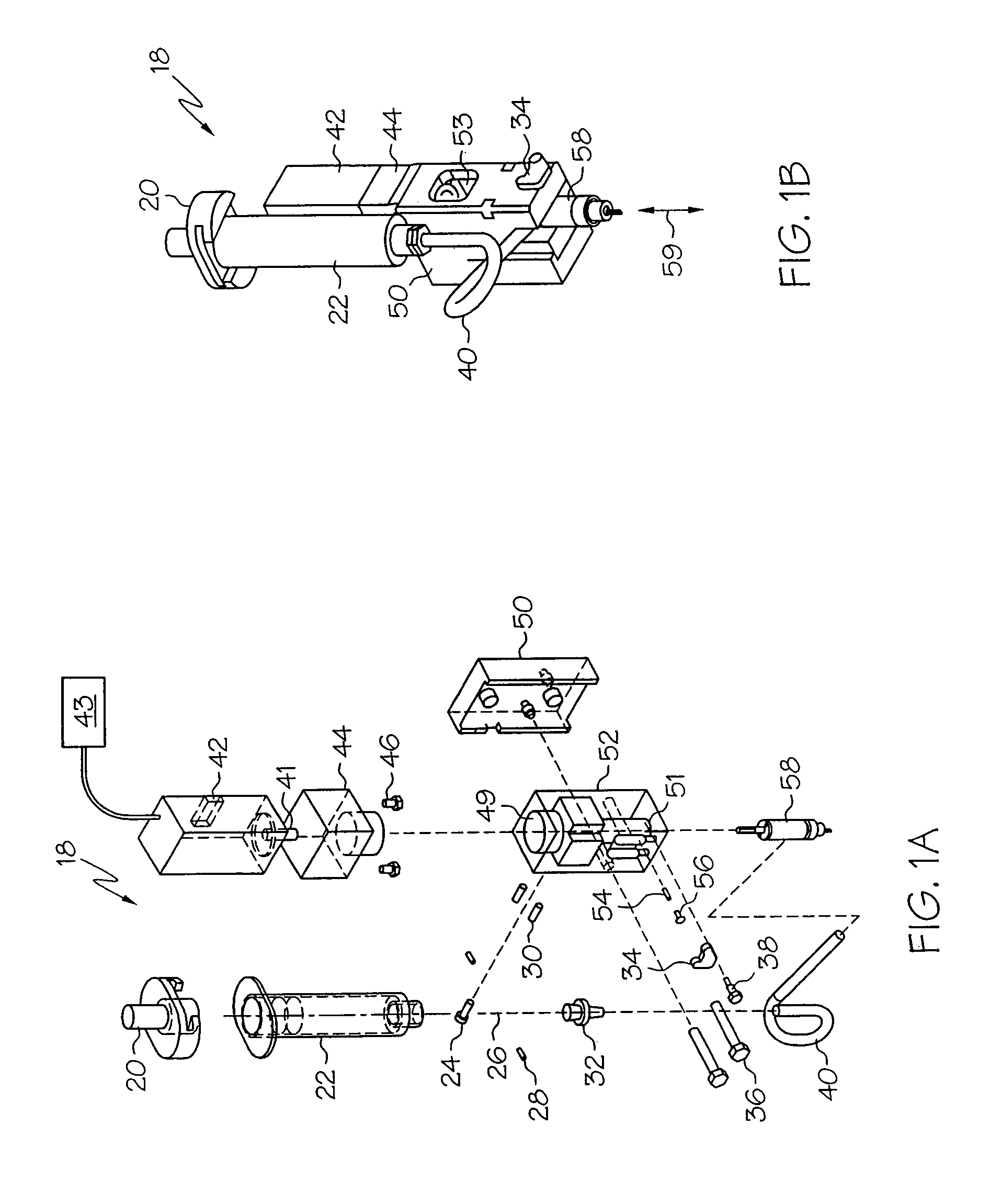
Since the tube and bracket are on opposite sides of the bracket, removal of the
syringe from the pump body requires dismantling of the tube and
syringe, which can contaminate fluid material positioned at the interface during disassembly.
Further, since the
syringe and
cartridge can not be removed and stored together as a unit, disassembly and cleaning of the
cartridge is required.
Additionally, the inlet neck is narrow and therefore difficult to clean.
While such pumps are adequate for operations requiring relatively large dispensing volumes, at smaller volumes the system resolution is relatively limited, since the timing
signal is relatively inaccurate at shorter time periods, and since residual motion in the
clutch or
brush motor is difficult to predict.
Assuming the platform / pump controller to be a computer-based system, the time-period-based
signal may be subject to even further variability, since
initiation of the
signal may be delayed while other tasks are processed by the computer.
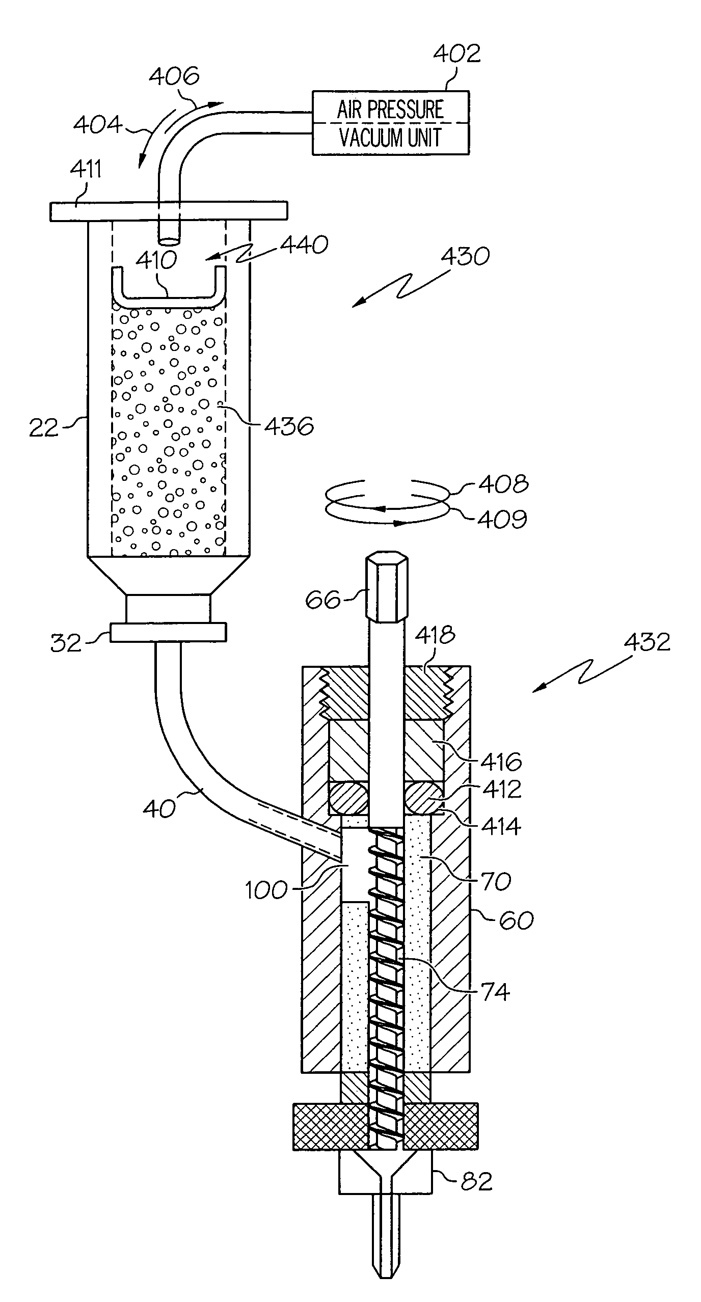
Conventional dispensing pumps are further limited in that following a dispensing operation, or in between dispensing operations, material can continue to flow, or drip, from the pump and dispense tip.
This can lead to excessive dispensing of the fluid, for example in the form of greater dispensed
fluid volume than desired, or the dripping of fluid at undesired locations on the substrate.
This is especially problematic for dispensing of materials of relatively low
viscosity, which tend to flow or drip more freely.
Others have attempted to address this problem, with limited success.
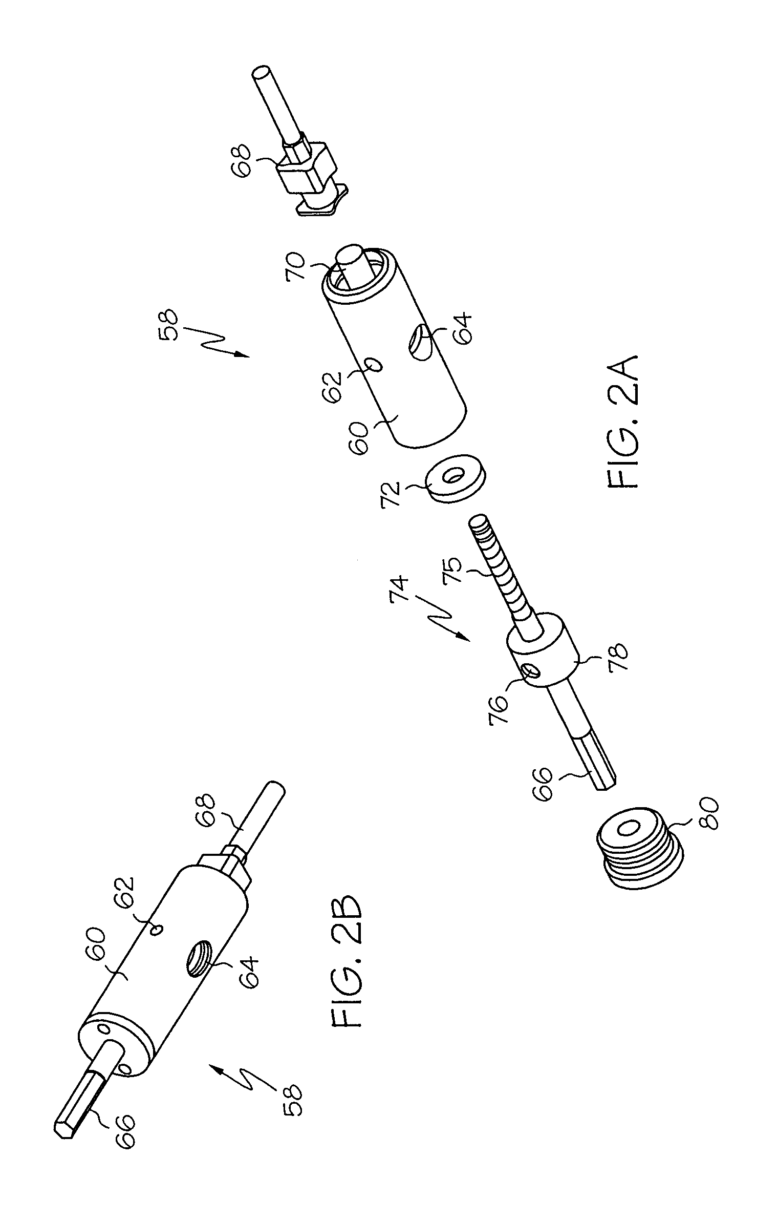
This system is however mechanically complex, owing to the number of
moving parts, and can cause eventual wear on the inlet of the dispensing needle, where the
auger screw comes in contact with the needle when in a sealed position.
In addition, the vertical position of the
auger must be set, which can further complicate setup and maintenance of the system.
Wear and improper settings can lead to inaccurate volume dispensing, and mechanical complexity can lead to jamming.

