Device and method for inducing sputum and collecting samples

Inactive Publication Date: 2006-01-10
MEDICAL ACOUSTICS
View PDF23 Cites 76 Cited by
  • Summary
  • Abstract
  • Description
  • Claims
  • Application Information

AI Technical Summary

Benefits of technology

[0009]The present invention can provide a device and method for artificially vibrating a patient's lungs to cause a viscosity change in mucus cont

Problems solved by technology

Typically, human lungs are too small to produce low-frequency audio sound.
A patient can blow

Method used


Image

  • Device and method for inducing sputum and collecting samples
  • Device and method for inducing sputum and collecting samples
  • Device and method for inducing sputum and collecting samples

Examples


Example

[0034]Exemplary embodiments of the present invention will be described below with reference to FIGS. 1–12 in which the same reference numerals represent similar elements.

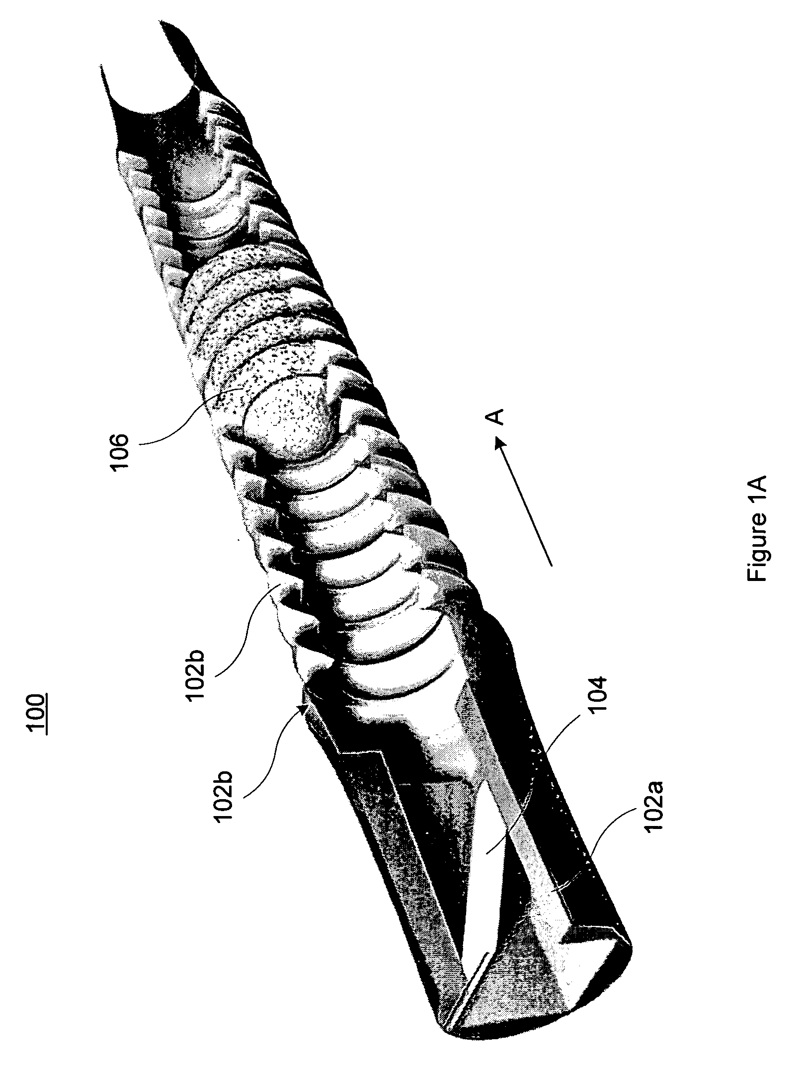
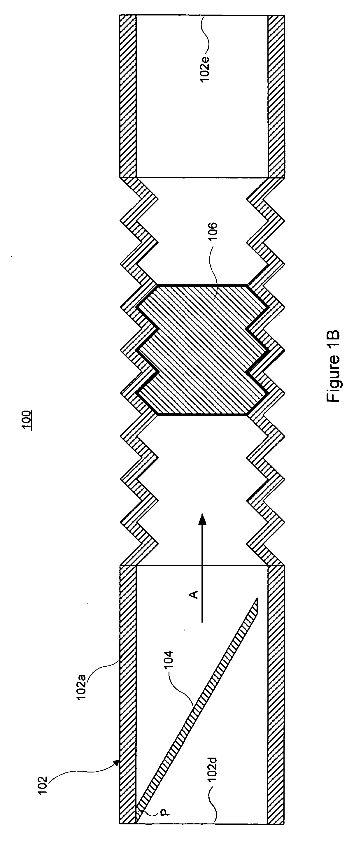
[0035]FIG. 1A illustrates a perspective, cut-away view of a lung vibrating device 100 according to an exemplary embodiment of the present invention. FIG. 1B illustrates a cross-sectional, side view of the exemplary lung vibrating device 100. The device 100 comprises an unpowered, disposable audio noisemaker. As shown in FIGS. 1A and 1B, the device 100 comprises a harmonica-type, free reed 104 in a housing 102. The device 100 also comprises an acoustical resistance 106 disposed within the housing 102.

[0036]The housing 102 can comprise a standard respiratory tube or other suitable material. As shown, the reed 104 can be coupled at point P to an insert 102a disposed in the housing 102. Alternatively, the reed 104 can be provided in a separate end cap (not shown) that couples to an end of the housing 102. The reed 104 c...


PUM


Abstract

A device for thinning lung secretions comprises a housing, a reed disposed in the housing, and an acoustical resistance. The reed produces a low-frequency audio shockwave in a range of about 12 Hz to about 30 Hz when vibrated. The acoustical resistance couples a patient lung cavity to the audio shockwave, thereby vibrating the patient's lung cavity to thin lung secretions.

Description

PRIORITY AND RELATED APPLICATIONS[0001]This application is a continuation-in-part of and claims the benefit of priority to U.S. Non-Provisional patent application Ser. No. 10 / 274,715, entitled “Device and Method for Inducing Sputum,” filed Oct. 21, 2002 (now U.S. Pat. No. 6,702,769), which claims the benefit of priority to U.S. Provisional Patent Application No. 60 / 346,343, entitled “Lung Cleaning Device,” filed Jan. 7, 2002. The complete disclosure of the above-identified priority applications is fully incorporated herein by reference.FIELD OF THE INVENTION[0002]The present invention relates generally to vibrating a patient's lungs to reduce the viscosity of mucus contained therein. More particularly, the present invention relates to a device and method for vibrating a patient's lungs with low-frequency audio shockwaves.BACKGROUND OF THE INVENTION[0003]The human lungs comprise a natural means for clearing mucus. Human lungs contain tiny clearing cilia that vibrate at approximately ...

Claims


Application Information

Patent Timeline
IPC IPC(8): A61H1/00A61M1/00A61H23/02A61M16/00A61M16/08A63B23/18
CPCA61H23/0236A61M16/0006A61M16/08A63B23/18
Inventor FOWLER-HAWKINS, SANFORD ELLIOT
Owner MEDICAL ACOUSTICS
Why Eureka
Try Eureka