

Thermal control of a DUT using a thermal control substrate
a technology of thermal control substrate and dut, which is applied in the direction of muffler furnaces, furnaces, instruments, etc., can solve the problems that prior thermal control systems generally do not provide a sufficient amount of temperature control for wafers
- Summary
- Abstract
- Description
- Claims
- Application Information
AI Technical Summary
Benefits of technology
Problems solved by technology
Method used
Image

Examples
first embodiment
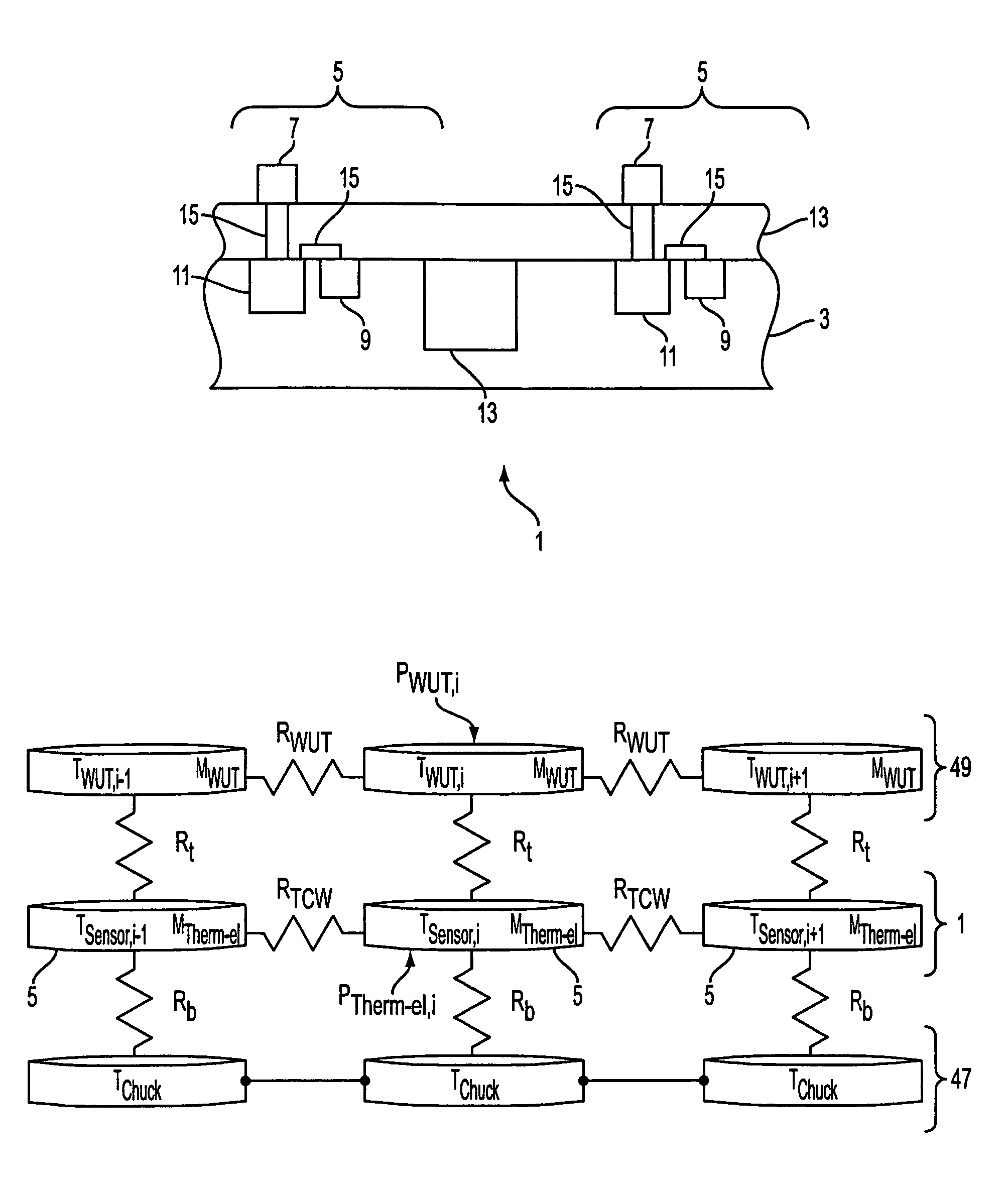
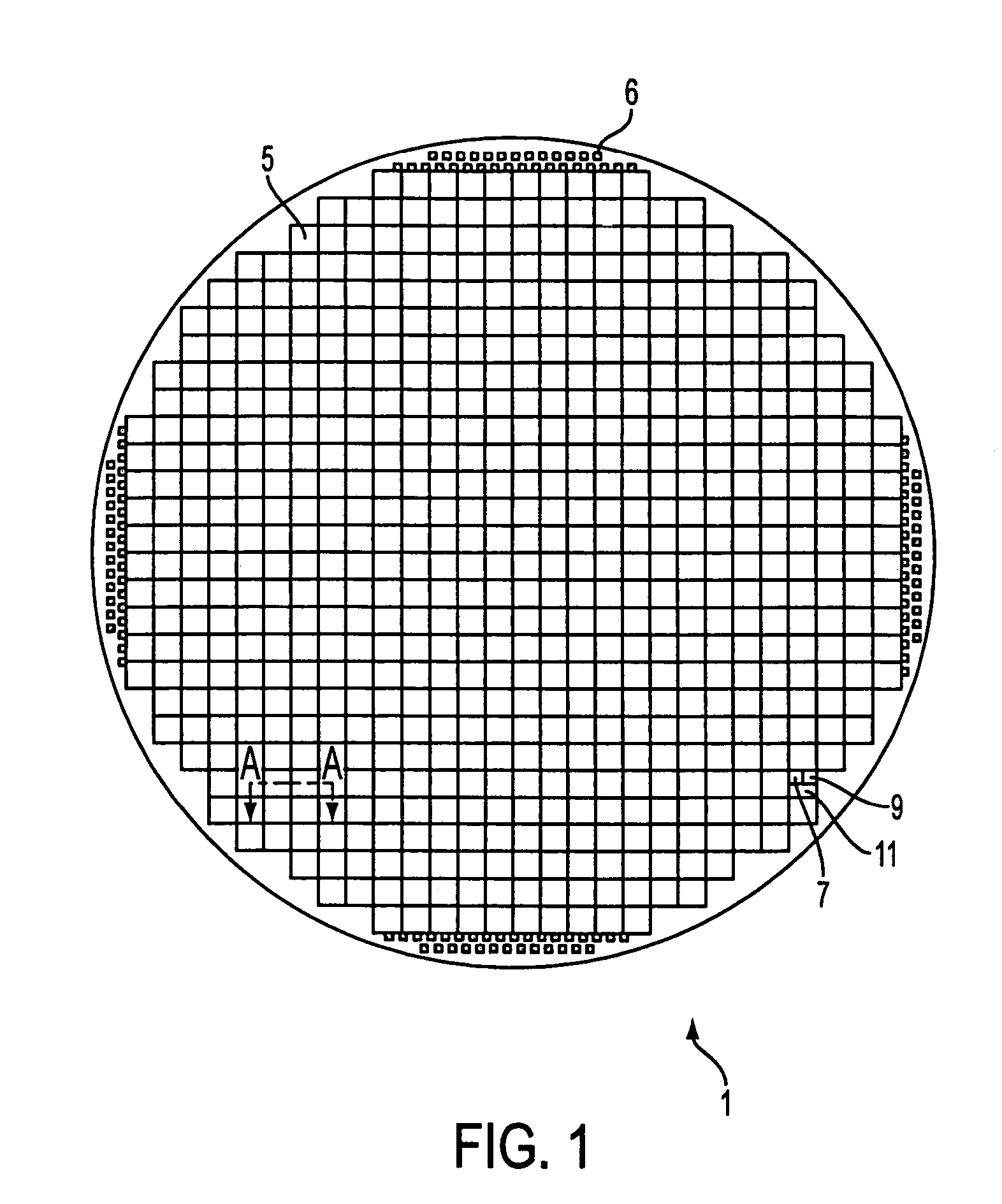
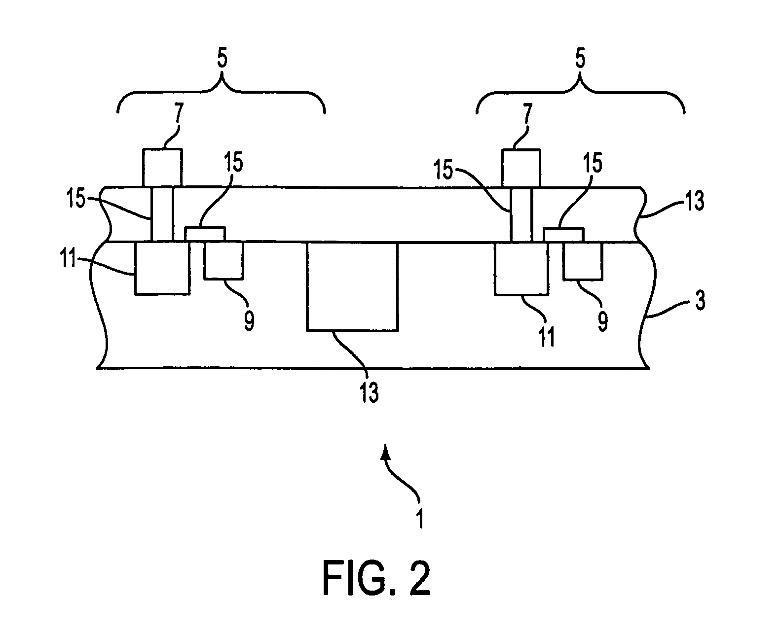
[0061]The Method Of The The thermal element control method according to the first preferred embodiment will now be described with respect to FIG. 9. The WUT temperature is extrapolated using a simplified thermal model. This method includes individually measuring a temperature of thermal elements 5 using temperature sensors 9 located on the TCW 1 (step 71), and extrapolating the temperature of the adjacent WUT region from these measurements (step 75). The temperature is preferably controlled in a closed feedback loop for each thermal element.
[0062]The measured temperature data is provided to the plurality of logic circuits 11 (step 73). Preferably, each temperature sensor 9 provides data to the circuit 11 located in the same thermal element 5, as described with respect to FIG. 3 above. The temperature sensor 9 output, a continuous waveform whose frequency varies with temperature, is provided into a counter 21 of the circuit 11. The counter 21 measures the frequency of the signal fro...
third embodiment
[0089]The Method Of The The thermal element control method according to the third preferred embodiment will now be described with respect to FIG. 11. This method uses direct feedback of WUT device temperature. In this embodiment, the temperature sensors are located directly on the WUT, preferably in each WUT die. In this embodiment, a physical mapping of WUT sensor to TCW thermal element is established. Then the thermal element heater powers are modulated to maintain a set point or target temperature based on measurements made by the WUT sensors (steps 91, 93).
[0090]The direct WUT temperature feedback temperature control method is more accurate than the methods of the first and second embodiments because it does not rely on thermal models and extracted parameters. Furthermore, the thermal elements may be simplified, such as thermal elements having a passive control circuit and no temperature sensors. Since the feedback originates from off the TCW, the WUT temperature values may be ...
fourth embodiment
[0091]The Method Of The The thermal element control method according to the fourth preferred embodiment will now be described with respect to FIG. 12. This method uses direct feedback of WUT device power dissipation. In this method, the WUT power dissipation is determined (step 101) and the heating of the WUT by the thermal elements is adjusted based on the determined WUT power dissipation (step 103). This “power following” temperature control method for thermal control of single packaged devices undergoing test is disclosed in PCT Application PCT / US99 / 15846 filed on Jul. 14, 1999, which corresponds to U.S. application Ser. No. 09 / 352,760, filed Jul. 14, 1999, both incorporated herein by reference in their entirety.
[0092]In the single device power following mode described in these applications, an isothermal heater and thermometer are connected to the DUT through a thermal resistance Rt and to a thermal reservoir through a thermal resistance Rb. The test system provides a signal to...
PUM
 Abstract
Description
Claims
Application Information