Radio antenna apparatus provided with controller for controlling SAR and radio communication apparatus using the same radio antenna apparatus

a radio antenna and controller technology, applied in the direction of resonant antennas, substation equipment, different interacting antenna combinations, etc., can solve the problems of insufficient reduction effect of sar and all radio waves radiated from the radio communication apparatus, and achieve the effect of reducing an sar

Active Publication Date: 2006-01-10
PANASONIC INTELLECTUAL PROPERTY CORP OF AMERICA
View PDF18 Cites 100 Cited by
  • Summary
  • Abstract
  • Description
  • Claims
  • Application Information

AI Technical Summary

Benefits of technology

[0009]It is an object of the present invention to provide a radio antenna apparatus and a radio communication apparatus including the same radio antenna apparatus, each capable of shielding substantially almost all radio waves radiated from a radio communication apparatus from a human body, with a configuration simpler than that of prior art, thereby remarkably reducing an SAR.
[0028]Therefore, according to the radio antenna apparatus and the radio communication apparatus using the same radio antenna apparatus, substantially almost all radio waves radiated from a radio communication apparatus can be shield from a human body, with a configuration simpler than that of prior art, thereby remarkably reducing an SAR.

Problems solved by technology

However, the shape of the conductor plate 1113 according to the prior art is restricted, so that all the radio waves radiated from the radio communication apparatus cannot be shielded.
Therefore, the effect of reduction of the SAR is insufficient only by shielding a part of the radio waves.

Method used


Image

  • Radio antenna apparatus provided with controller for controlling SAR and radio communication apparatus using the same radio antenna apparatus
  • Radio antenna apparatus provided with controller for controlling SAR and radio communication apparatus using the same radio antenna apparatus
  • Radio antenna apparatus provided with controller for controlling SAR and radio communication apparatus using the same radio antenna apparatus

Examples


first preferred embodiment

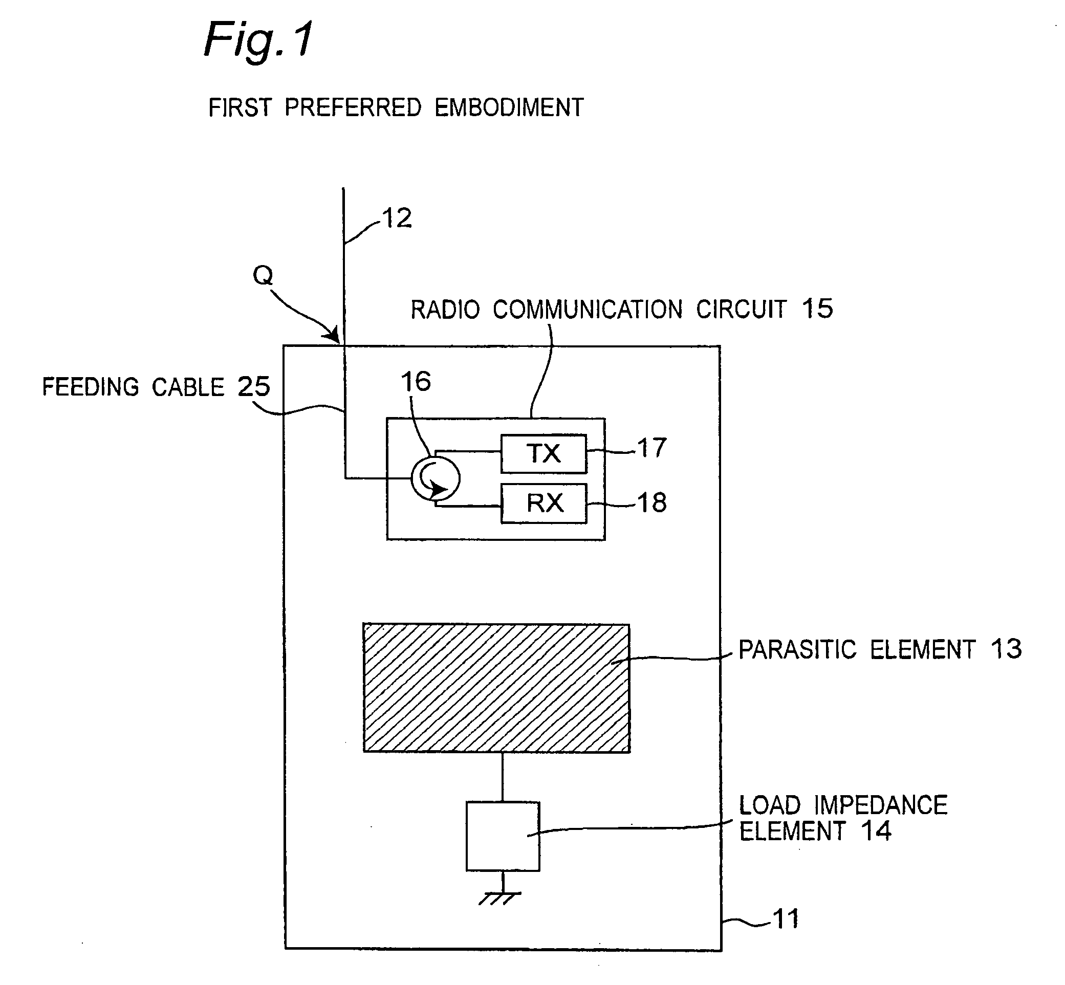
[0085]FIG. 1 is a block diagram showing a configuration of a radio communication apparatus including a radio antenna according to a first preferred embodiment of the present invention.

[0086]Referring to FIG. 1, a radio communication circuit 15 provided in a housing 11 of the radio communication apparatus includes a radio transmitter circuit 17, a radio receiver circuit 18, and a circulator 16 for sharing one-quarter-wave whip antenna 12 between the two circuits 17 and 18. The radio transmitter circuit 17 executes processings including modulation, high frequency conversion and power amplification on an input voice signal or an input data signal, and then, generates a radio transmitted signal. The radio transmitted signal is outputted to the whip antenna 12 through the circulator 16, a feeding cable 25, and a feeding point Q, and then, a radio wave of the radio transmitted signal is radiated from the whip antenna 12. A radio received signal received by the whip antenna 12 is inputted ...

second preferred embodiment

[0104]FIG. 8 is a block diagram showing a configuration of a radio communication apparatus including a radio antenna according to a second preferred embodiment of the present invention. As shown in FIG. 8, the radio communication apparatus according to the second preferred embodiment includes a whip antenna 12 extending upward from an upper portion of a housing 11, and a plane antenna 23 provided in the housing 11, where the two antennas 12 and 23 constitute a space diversity system.

[0105]Referring to FIG. 8, the radio communication apparatus includes the plane antenna 23 and two load impedance elements 31 and 41, which are provided in the housing 11. The plane antenna 23 is, for example, a rectangular-plane-shaped electrical conductor plate, and it is provided, for example, so as to be parallel to a front surface (corresponding to the head of a human body that is a user) of the housing 11 in the vicinity of the front surface of the housing 11 to be electromagnetically connected wit...

third preferred embodiment

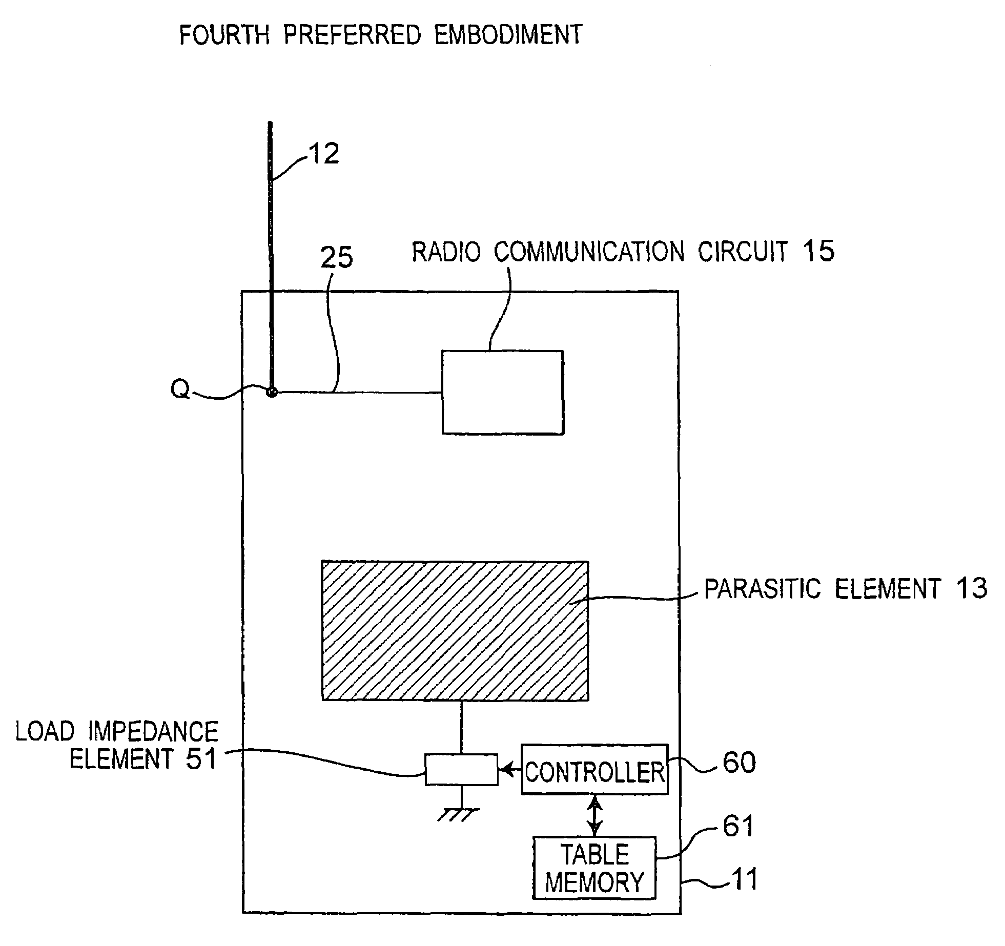
[0112]FIG. 9 is a block diagram showing a configuration of a radio communication apparatus including a radio antenna according to a third preferred embodiment of the present invention. As shown in FIG. 9, the radio communication apparatus according to the third preferred embodiment is characterized by including a whip antenna 12 extending upward from an upper portion of a housing 11, and a plane antenna 23 provided in the housing 11, where the two antennas 12 and 23 constitute a space diversity system. Further, one load impedance element 51 and one changeover switch 52 capable of changing the reactance X are provided in place of the two load impedance elements 31 and 41 and the two switches 32 and 42 according to the second preferred embodiment shown in FIG. 8.

[0113]Referring to FIG. 9, the plane antenna 23 and the load impedance element 51 are provided in the housing 11. The plane antenna 23 is, for example, a rectangular-plane-shaped electrical conductor plate and provided, for ex...


PUM


Abstract

A radio antenna apparatus is provided with an antenna connected with a radio communication circuit that transmits and receives a radio signal. A load impedance element is connected between a parasitic element of an electrical conductor plate and a ground of a housing of a radio communication apparatus including the radio communication circuit. A controller controls an element value of the load impedance element so as to set a current flowing on the housing to be equal to or smaller than a predetermined value when the radio communication apparatus transmits the radio signal, thereby controlling a specific absorption rate (SAR) to be equal to or smaller than a predetermined value.

Description

BACKGROUND OF THE INVENTION[0001]1. Field of the Invention[0002]The present invention relates to a radio antenna apparatus provided with a controller for controlling a specific absorption rate (referred to as an SAR hereinafter), and a radio communication apparatus using the same radio antenna apparatus, such as a portable telephone, a car telephone, or the like.[0003]2. Description of the Related Art[0004]Recently, radio communication apparatuses such as a portable telephone and a car telephone have rapidly spread. The size of each of these radio communication apparatuses has been increasingly reduced year by year. Because of reduction in size of the radio communication apparatus, radio waves are radiated not only from an antenna but also from a housing of the radio communication apparatus. That is, electromagnetic waves are radiated from the entire radio communication apparatus.[0005]A part of the electromagnetic wave radiated from the antenna and the radio communication apparatus...

Claims


Application Information

Patent Timeline
Patent Type & Authority Patents(United States)
IPC IPC(8): H01Q1/24H01Q3/44H01Q19/26H01Q21/29H04B1/38
CPCH01Q1/245H01Q3/44H04B1/3838H01Q21/29H01Q19/26
Inventor NISHIMURA, SHOTAROYAMAMOTO, ATSUSHIOGAWA, KOICHIIWAI, HIROSHI
Owner PANASONIC INTELLECTUAL PROPERTY CORP OF AMERICA
Why Eureka
Try Eureka