Cache lock mechanism with speculative allocation

a lock mechanism and cache technology, applied in the field of data processing systems, can solve the problems of cache memory subsystem efficiency, certain types of memory access requests not supporting a non-blocking schem

Inactive Publication Date: 2006-01-10
INTEL CORP
View PDF4 Cites 20 Cited by
  • Summary
  • Abstract
  • Description
  • Claims
  • Application Information

AI Technical Summary

Problems solved by technology

Another factor affecting performance of microprocessors is the efficiency of the cache mem

Method used


Image

  • Cache lock mechanism with speculative allocation
  • Cache lock mechanism with speculative allocation
  • Cache lock mechanism with speculative allocation

Examples


Embodiment Construction

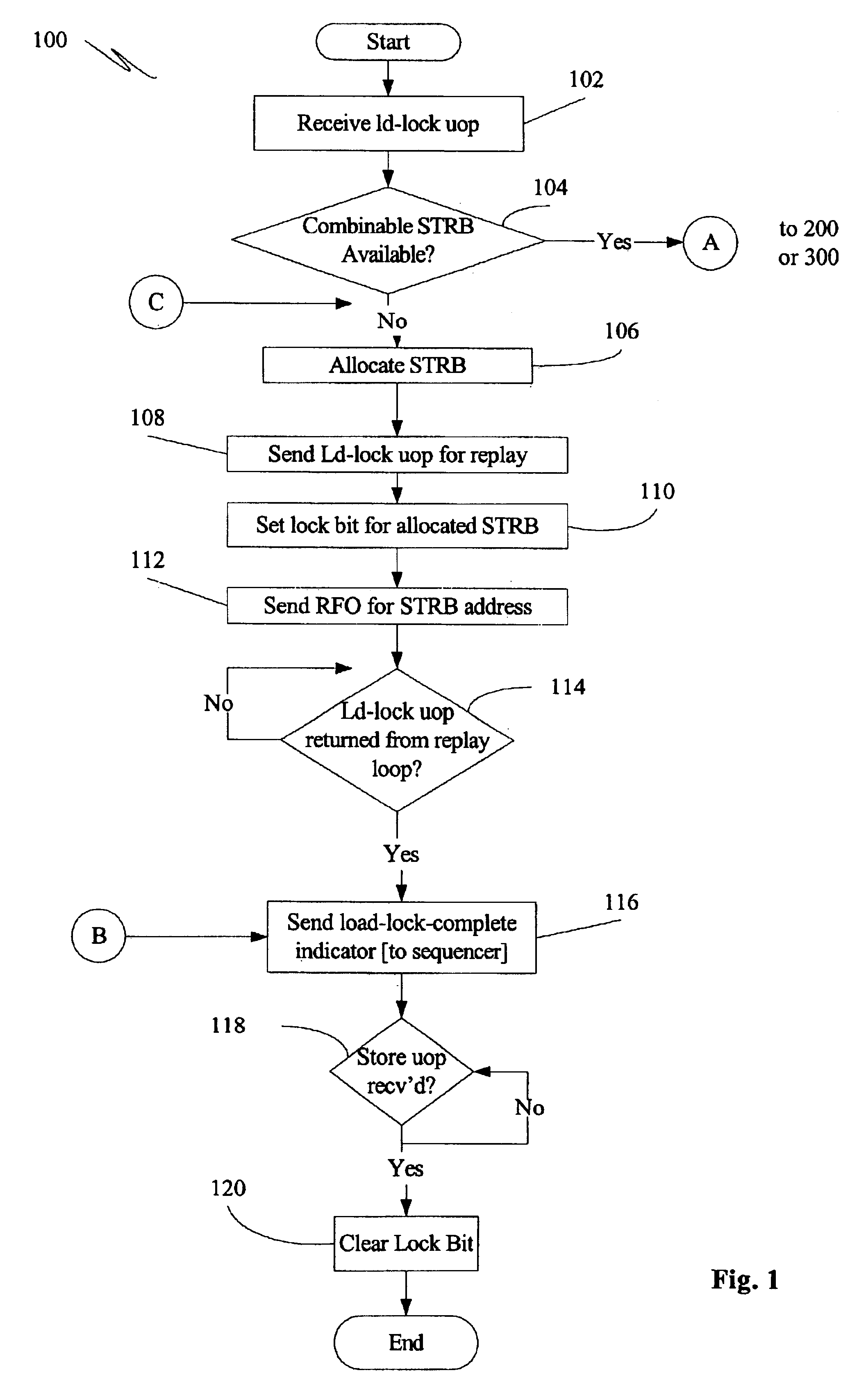
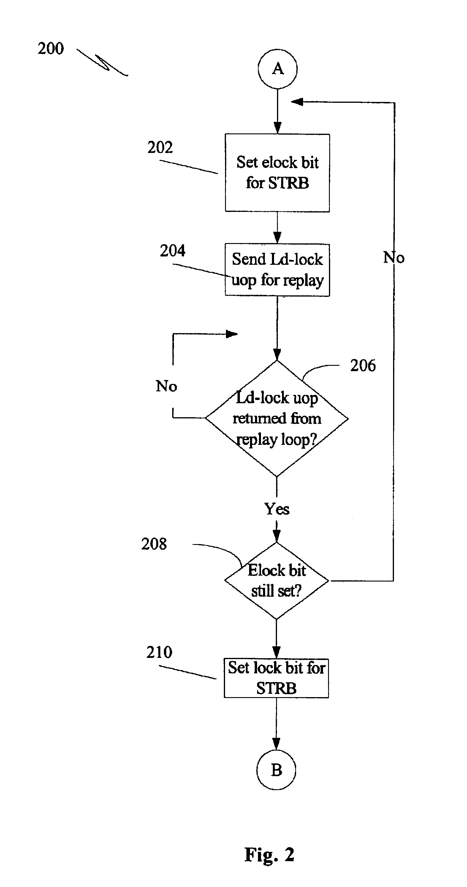
[0016]FIG. 1 is a flowchart illustrating a general mechanism for performing a cache lock when an existing store request buffer is not available for the address targeted by the cache lock operation. FIGS. 2 and 3 are flowcharts illustrating methods 200, 300 for performing a cache lock when a current combinable store request buffer (“STRB”) for the requested lock address is present. FIG. 2 illustrates a method 200 according to at least one embodiment of the present invention, while FIG. 3 illustrates a method 300 that performs a less efficient STRB entry eviction approach.

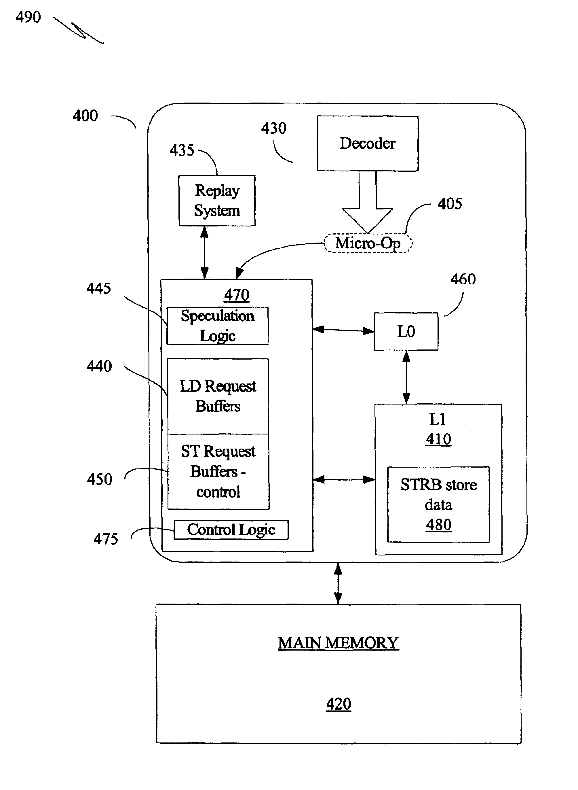
[0017]FIGS. 1, 2 and 3 will be discussed with reference to FIG. 4. FIG. 4 is a block diagram illustrating at least one embodiment of processor 400 capable of employing a speculative cache lock allocation method 200 as illustrated in FIG. 2. FIG. 4 illustrates a processor 400 that implements a non-blocking cache memory subsystem (the cache memory subsystem will sometimes be referred to herein by the shorthand terminol...


PUM


Abstract

A method and apparatus to speculatively allocate a combinable store request buffer for a cache lock operation by setting an extended lock indicator. The store request buffer is speculatively allocated and the load-lock micro-operation associated with the cache lock operation is sent to a replay loop. During the replay window, conflict detection processing is completed. When the load-lock micro-operation returns from replay, the store buffer is de-allocated if a conflict has been detected during the replay window.

Description

BACKGROUND[0001]1. Technical Field[0002]The present invention relates to systems for processing data and, more particularly, to systems employing a cache lock / unlock protocol for non-blocking caches.[0003]2. Background Art[0004]Microelectronic manufacturers are continually striving to improve the speed and performance of microprocessors and other processing devices, the performance of such devices being dependent upon many factors. One factor affecting the performance of a processor is the scheduling and execution of instructions associated with a piece of code executing on the processor. Many processors include an instruction decoder that decodes an instruction to create one or more micro-instructions, or micro-operations, that can be understood and executed by the processor. Micro-instructions and micro-operations will be referred to herein, in the singular, as a “μOP.” Micro-operations ready for execution are provided to a scheduler, which schedules the order of execution for a s...

Claims


Application Information

Patent Timeline
IPC IPC(8): G06F12/14G06F12/00G06F12/08
CPCG06F12/0802
Inventor SUTANTO, EDWIN R.CHEONG, HOICHILIN, ZHONGRU J.NYE, JEFFREY L.
Owner INTEL CORP
Why Eureka
Try Eureka