Four-degree-of freedom piezoelectric micro-clamp

A micro-clamp, degree-of-freedom technology, applied in the direction of chucks, circuits, relays, etc., can solve the problems of increased complexity, design difficulty and cost of micro-assembly and micro-operating system, and reduce the design difficulty and complexity. , the effect of reducing mass and volume, reducing cost

Active Publication Date: 2015-11-18
NINGBO UNIV
View PDF11 Cites 18 Cited by
  • Summary
  • Abstract
  • Description
  • Claims
  • Application Information

AI Technical Summary

Problems solved by technology

[0003] Each finger of the current micro gripper has only one degree of freedom in the clamping direction, and the whole micro gripper has only two degrees of freedom, which can only realize the movement in the gripping direction, and the movement in other directions must pass through the actuator at the front end This increases the complexity and design difficulty of the entire micro-assembly and micro-operating system, and increases the cost

Method used


Image

  • Four-degree-of freedom piezoelectric micro-clamp
  • Four-degree-of freedom piezoelectric micro-clamp
  • Four-degree-of freedom piezoelectric micro-clamp

Examples


Embodiment 1

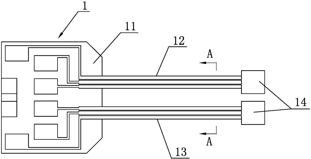
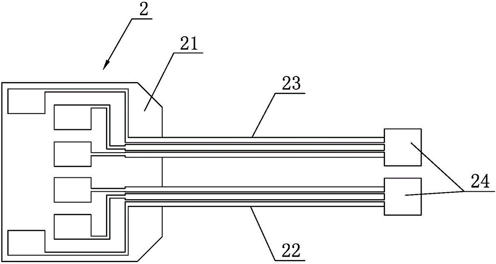
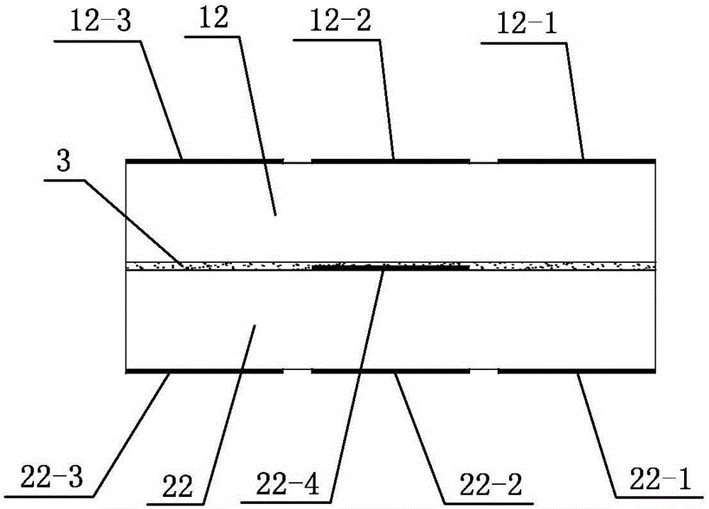
[0020]Embodiment 1: As shown in the figure, a four-degree-of-freedom piezoelectric micro-clamp includes an upper piezoelectric ceramic wafer 1 and a lower piezoelectric ceramic wafer 2, and the bonding surface of the upper piezoelectric ceramic wafer 1 and the lower piezoelectric ceramic wafer The bonding surfaces of the wafer 2 are bonded and fixed by insulating glue 3. The upper piezoelectric ceramic wafer 1 includes an upper support portion 11 and an upper left clamp finger 12 and a right upper clamp finger 13 integrally connected to the upper support portion 11. The finger portion 12 and the upper right pincer finger portion 13 are symmetrical along the center line of the upper support portion 11, and the free ends of the upper left pincer finger portion 12 and the free ends of the upper right pincer finger portion 13 are integrally provided with upper extensions that can be used to install different clamping heads. part 14, the lower piezoelectric ceramic wafer 2 includes ...

Embodiment 2

[0021] Embodiment 2: a kind of four-degree-of-freedom piezoelectric micro-clamp, comprising an upper piezoelectric ceramic wafer 1 and a lower piezoelectric ceramic wafer 2, the bonding surface of the upper piezoelectric ceramic wafer 1 and the lower piezoelectric ceramic wafer 2 The surfaces are bonded and fixed by insulating glue 3. The upper piezoelectric ceramic wafer 1 includes an upper support part 11 and an upper left clamp finger part 12 and a right upper clamp finger part 13 integrally connected to the upper support part 11. The pliers fingers 13 are symmetrical along the center line of the upper support 11, and the free ends of the upper left pliers fingers 12 and the free ends of the upper right pliers fingers 13 are respectively integrally provided with upper extensions 14 that can be used to install different clamping heads. The electric ceramic wafer 2 includes a lower support part 21 and a lower left clamp finger part 22 and a right lower clamp finger part 23 int...


PUM


Abstract

The invention discloses a four-degree-of-freedom piezoelectric micro-clamp. The four-degree-of-freedom piezoelectric micro-clamp has the following advantages: the piezoelectric micro-clamp can enable each clamp finger to realize actions in a clamping direction and a direction perpendicular to the clamping direction, that is, each clamp finger has degrees of freedom in two directions; and the whole piezoelectric micro-clamp has four degrees of freedom, so that part front end execution mechanisms of micro-assembly and micro-operation systems can be saved, the design difficulty and complexity of the system are reduced, the mass and the volume of the system are decreased, and the system cost is reduced.

Description

technical field [0001] The invention relates to the technical field of micro / nano positioning, belongs to the end effector in micro / nano positioning systems such as micro parts assembly and cell micro operation, and particularly relates to a four-degree-of-freedom piezoelectric micro clamp. Background technique [0002] Micro grippers are end effectors that can produce micron or nanometer-level motion precision and motion resolution. It can be applied to cutting-edge technical fields such as MEMS and bioengineering. In MEMS, micro-grippers can pick up and transport micro-parts such as micro-shafts and micro-gears, as well as micro-components such as micro-motors and micro-pumps; in bioengineering, micro-grippers are used to capture and release cells. Combined with the micro-impact probe, it can inject a certain component into the cell or extract a certain component from the cell. [0003] Each finger of the current micro gripper has only one degree of freedom in the clampin...

Claims


Application Information

Patent Timeline
Patent Type & Authority Applications(China)
IPC IPC(8): B25J7/00B25J15/08B23K26/38B81B5/00B81C3/00
Inventor 崔玉国冯锋义郑军辉蔡成波
Owner NINGBO UNIV
Why Eureka
Try Eureka