Punch for a ductile material joining tool

Inactive Publication Date: 2006-01-17
WADE COLIN MAXWELL
View PDF15 Cites 9 Cited by
  • Summary
  • Abstract
  • Description
  • Claims
  • Application Information

AI Technical Summary

Benefits of technology

[0023]The load spacer may also be used to help adjust or to set a correct rotational orientation of the punch relative to the punch holder or assembly. In one embodiment of the inv

Problems solved by technology

The lifetime of a punch assembly is limited essentially by wear of the punch tip, either of the punch surface itself or edges to the punch tip.
Such wear can be minimised if the punch tip is made from hardened steel (62 to 64 RC), but this increases the possibility of the punch tip breaking if the punch is not properly aligned with the die.
The punch tip may therefore be damaged in use if it is not properly aligned with the die.
The corner of the die blade facing inwards to the die recess normal

Method used


Image

  • Punch for a ductile material joining tool
  • Punch for a ductile material joining tool
  • Punch for a ductile material joining tool

Examples


Embodiment Construction

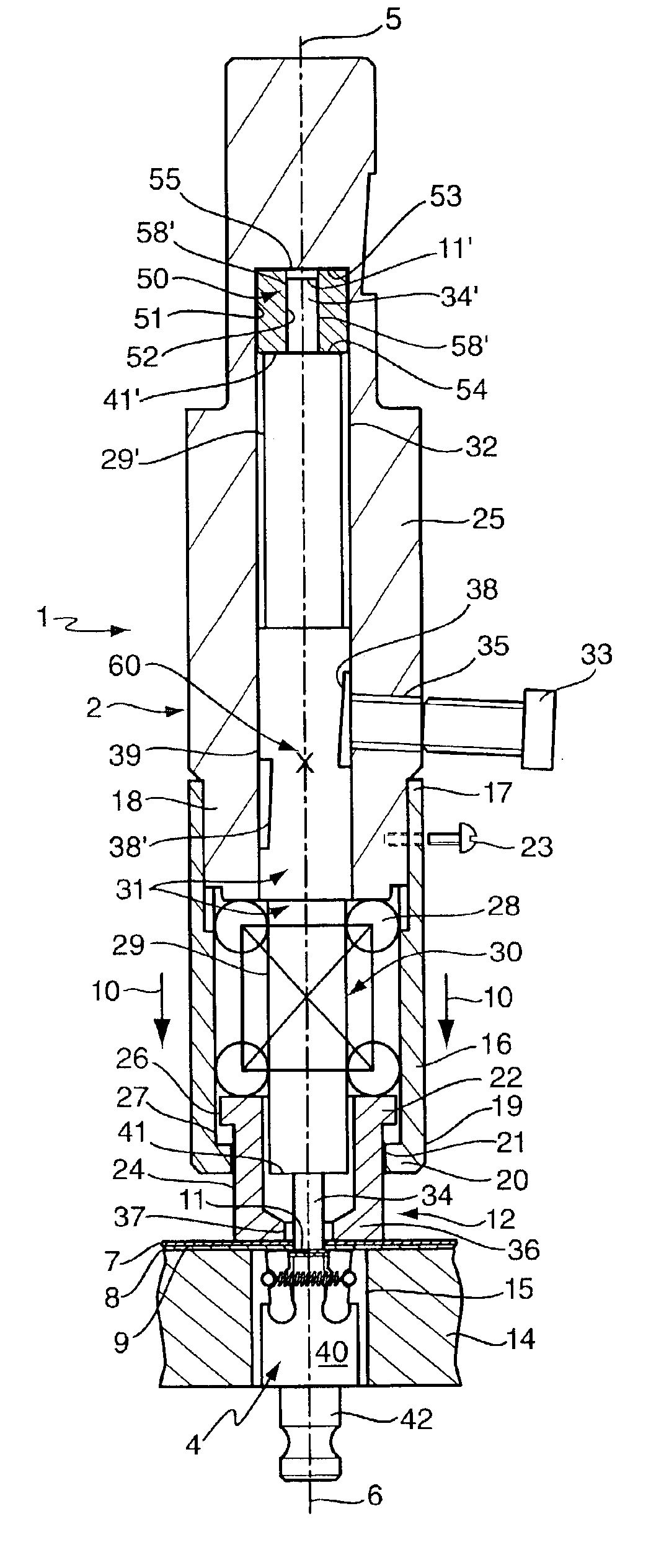
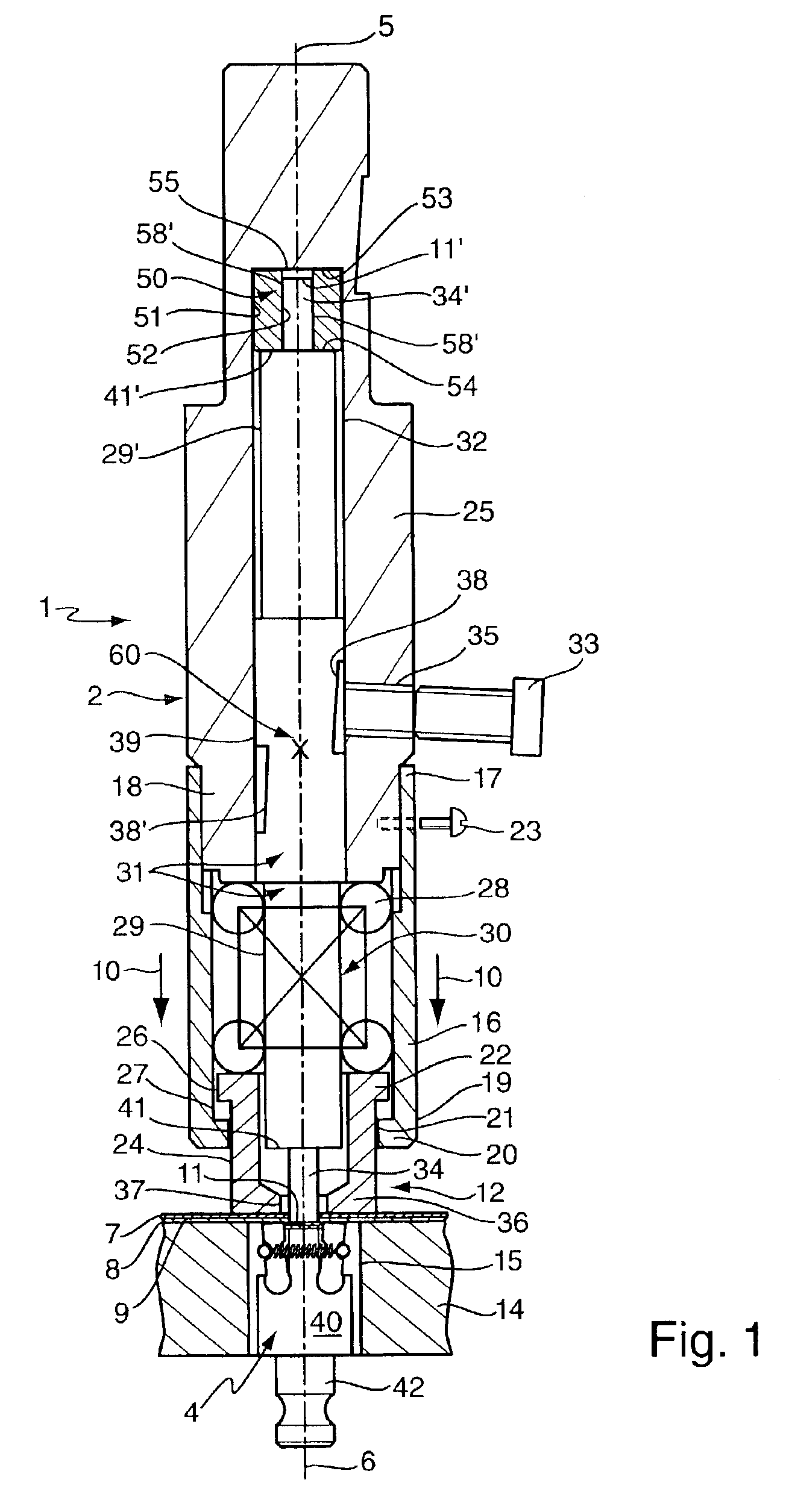
[0037]FIG. 1 shows a first embodiment of a ductile material joiner 1 according to a first embodiment of the invention. The joiner comprises a punch assembly 2 and a die assembly 4. The punch assembly 2 and die assembly 4 are aligned along common punch axes 5,6. Between the punch assembly 2 and die assembly 4 are a pair of thin ductile metal sheets 7,8 which are aligned transverse to the punch axes 5,6. The sheets 7,8 are in contact along a common interface 9.

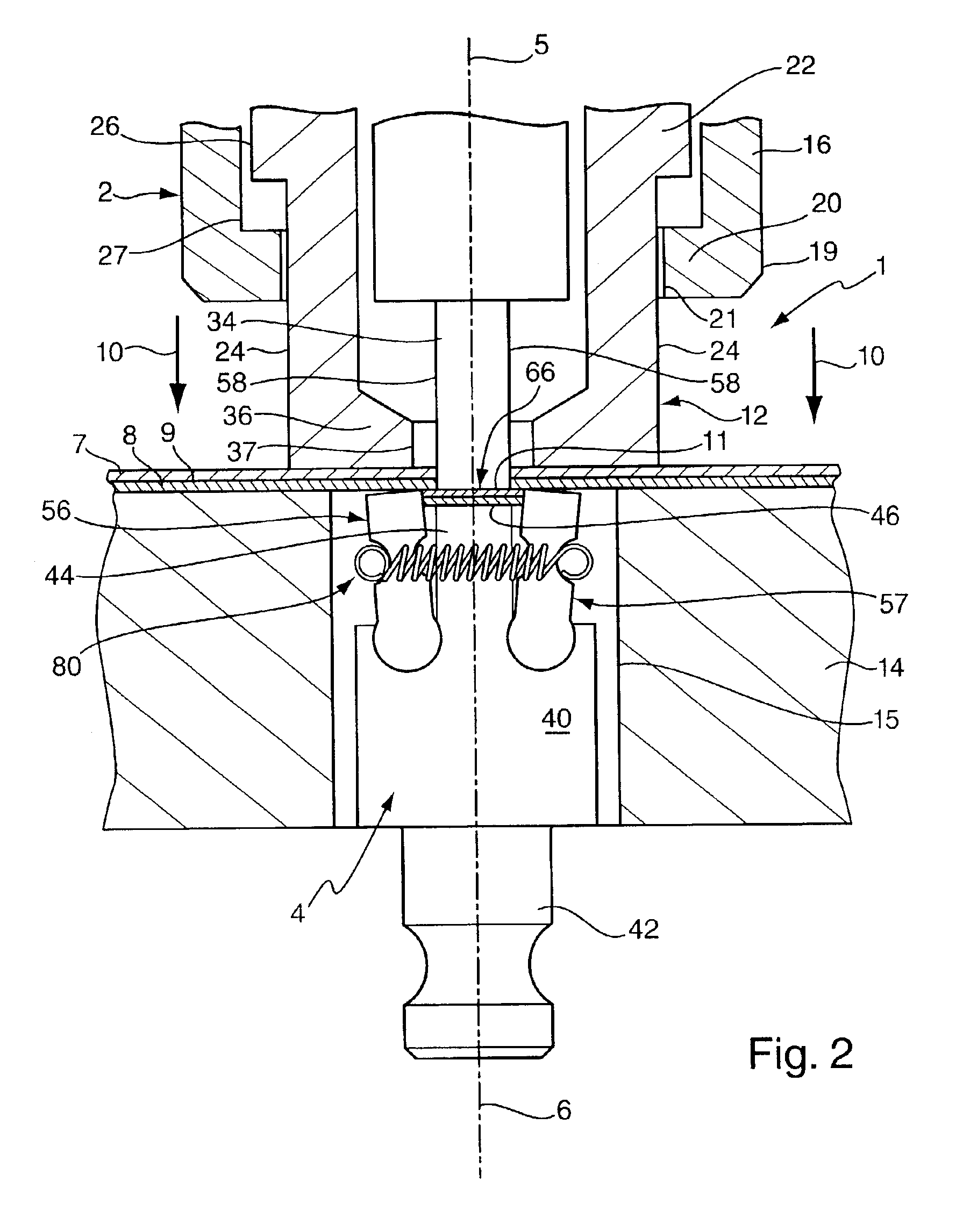
[0038]In a sheet material joining operation, the punch assembly 2 is brought towards the pair of sheets 7,8 along a longitudinal direction as indicated by movement arrows 10 until a forward hollow stripper tip 12 of the punch assembly 2 comes into contact with an upper one of the metal sheets 7, thereby pressing the other lower metal sheet 8 against a base plate 14 surrounding the die assembly 4. The base 14 plate has a recess 15 in which the die assembly 4 is removably seated.

[0039]The punch assembly 2 has a lower cylindrical h...


PUM

PropertyMeasurementUnit
Angleaaaaaaaaaa
Forceaaaaaaaaaa
Pressureaaaaaaaaaa

Abstract

The present invention relates to a punch (30) and punch assembly (2) for use in a tool (1) for joining ductile materials, such as metal sheets (7,8), in a lance joint or a clinch joint. The punch (30) has a punch body (31) formed around a punch axis (5). Two punch tips (34,34′) extend in opposite directions from the punch body (31) along the punch axis (5). The punch body has one or more load engagement features (41,41′) by which a punch force for joining the ductile materials (7,8) is imparted to the punch body (31). When one punch tip (34) becomes worn, the punch (30) can be removed from a punch holder (25), inverted and rejoined to the punch holder (25) so that the other of the punch tips (34′) can be used to join ductile material (7,8)

Description

BACKGROUND[0001]a. Field of the Invention[0002]The present invention relates to a punch for use in a tool for clinch joining ductile materials, such as metal sheets, and in particular to a punch for use with a lanced clinch joiner or a round clinch joiner.[0003]b. Related Art[0004]It is known to join a plurality of sheets of ductile material by causing these to be deformed into an interlocking configuration in a local area. Such joins are made by ductile material joining tools comprising a die with an aperture that is opposite a punch assembly comprising a punch. The punch has a punch tip, which may have a flat or rounded punch surface. The edges of the punch surface may be radiused, chamfered, or sharp. The punch itself may be surrounded by a stripper mechanism to facilitate removal of the punch from the deformed ductile material. Layers of ductile material are sandwiched between the punch assembly and when the punch tip punch is pressed towards the aperture, material is drawn into...

Claims


Application Information

Patent Timeline
IPC IPC(8): B26F1/14B21D39/03
CPCB21D39/031B21D39/035Y10S83/955Y10T83/9423Y10T83/943Y10T83/04
Inventor WADE, COLIN MAXWELL
Owner WADE COLIN MAXWELL
Why Eureka
Try Eureka