
Drawer slide

Inactive Publication Date: 2006-01-17
GRASS AMERICA
View PDF15 Cites 8 Cited by
  • Summary
  • Abstract
  • Description
  • Claims
  • Application Information

AI Technical Summary

Benefits of technology

[0006]The task of the present invention is a drawer slide with width equalization based on DE 299 23 509 U1, which can be adjusted in various ways, besides being easy to maintain and replace.
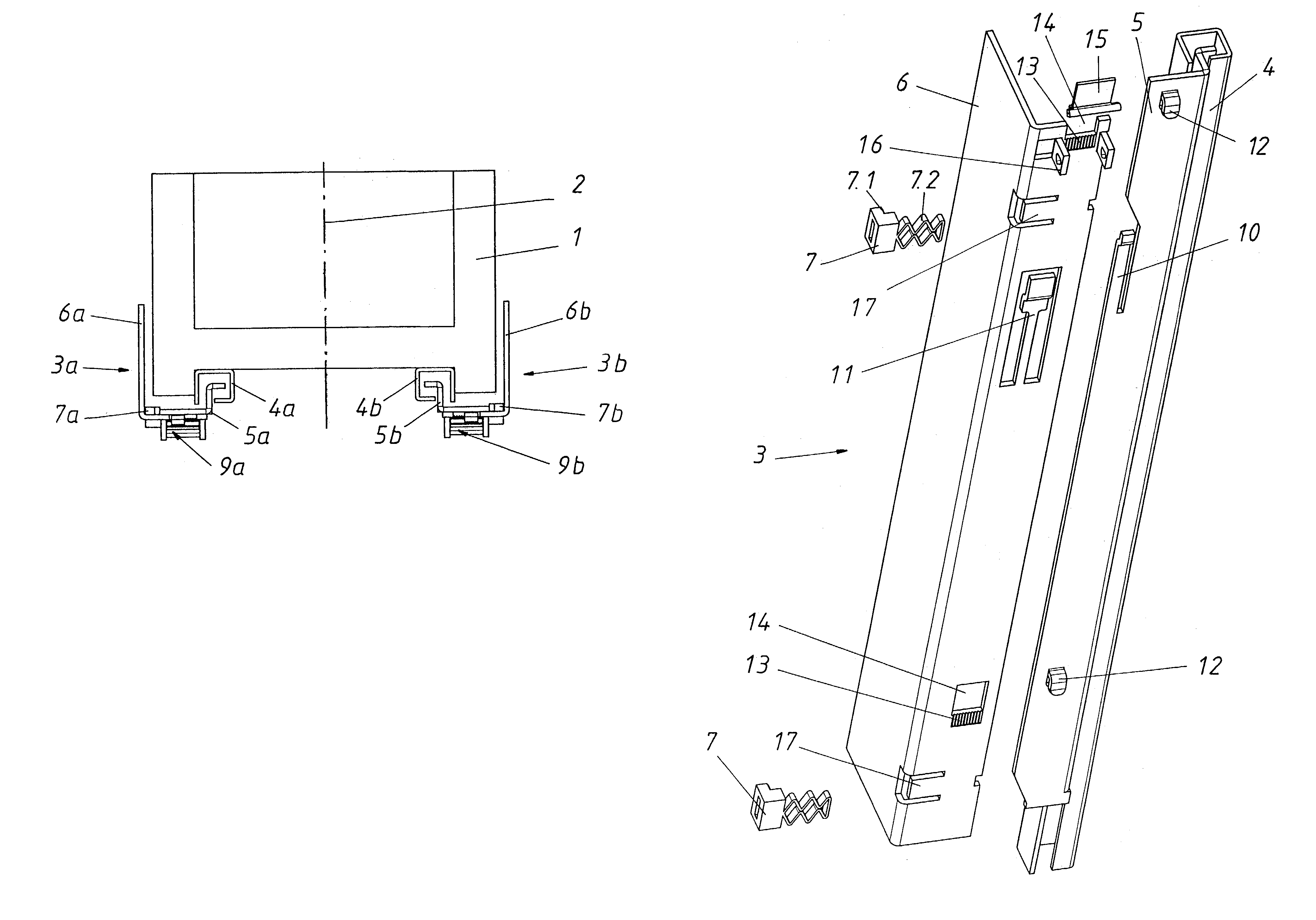
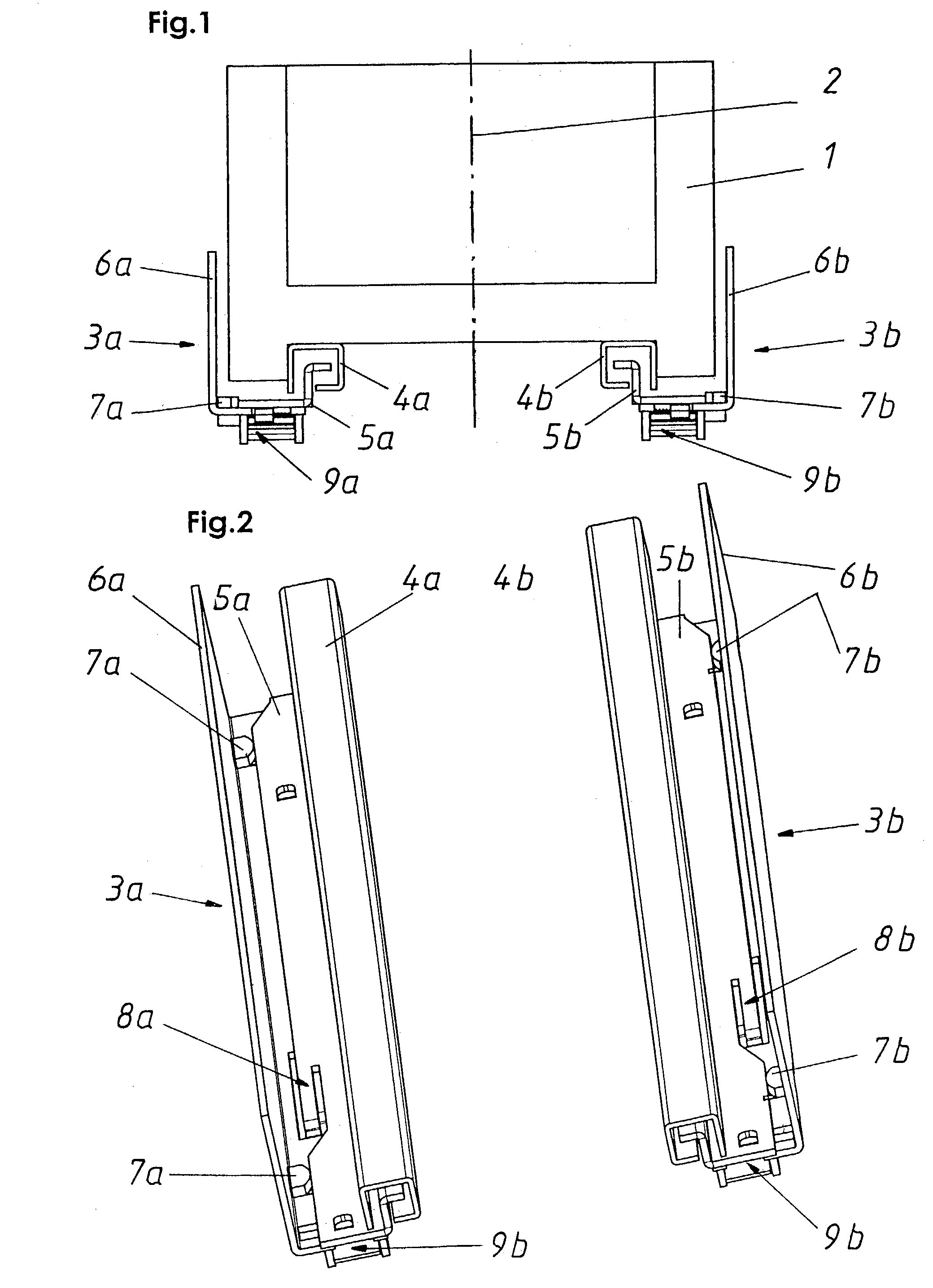
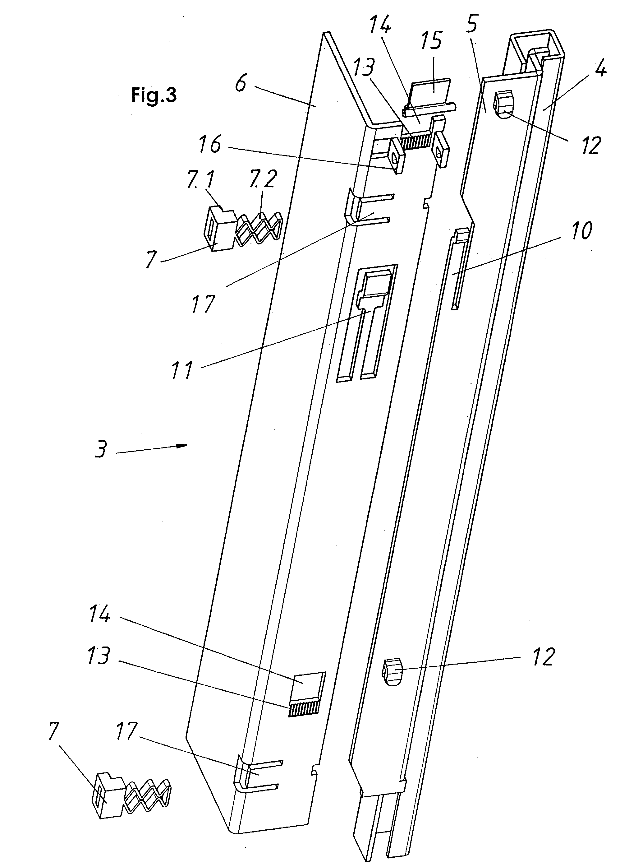
[0007]The fundamental characteristic of the invention is that at least one elastic springy / flexible width equalization element is located directly or indirectly between one of the cabinet-side slide rails and the cabinet body. The advantage here is now that the drawer, the cabinet-side and the insert-side slide rails can be installed to each other; whereas, before they were connected to the width equalization. This offers the basic and substantial advantage of the making the system more flexible, since the various pre-mounted drawer and slide rails can simply be combined with arbitrary or desired various width equalization elements, even at the place where the drawer is assembled. This arbitrary or desired combination between width equalization elements and guide rails can also later still be easily modified or altered after the initial assembly without having to remove the rails from the drawer or separating the rails.

Problems solved by technology

The disadvantage of this state-of-the-art centering mechanism is the fact that the whole lateral force, that works when, for example, the drawer is pushed in, must be transferred by the complicated mechanism and is, thus, exposed to increased wear.
Besides, this centering mechanism is expensive to produce and maintain.
The disadvantage of this design is that the centering mechanism for the drawer is located between the drawer and the insert-side slide rail and must, therefore, be pre-mounted.
This makes the system inflexible and makes replacement of the centering mechanism difficult in case of a defect.

Method used


Image

  • Drawer slide
  • Drawer slide
  • Drawer slide

Examples


first embodiment

[0050]FIGS. 6 and 7 show again a drawer slide (3) according to FIGS. 1–4, each with two end-sided located width equalization elements (7) as springy flexible centering parts per drawer slide element (3a,b). FIG. 7 shows a section along Line VII—VII of FIG. 6; whereby, the angle rail (6) and the cabinet-side slide rail (5), still not completely operational, are connected with one another.

[0051]FIGS. 5 and 8–11 also show a second embodiment with a flat spring (18) as a width equalization element, as well as a corresponding blocking device (22–24) of the flat spring (18). The same building components are again described with the same reference symbols as shown in FIGS. 1–4, 6 and 7 of the first embodiment.

second embodiment

[0052]FIG. 8 shows an exploded representation of the second embodiment with the flat spring (18) and the corresponding block device (22–24), which consists of a wedge surface slider (22) that has almost the same length as the leaf spring (18) and on the end side always has a wedge surface element (23) as well as at least one handle (24) on a side to slide manually.

[0053]Now FIG. 9 shows the drawer slide according to FIG. 8 in the assembled state, which should be recognized that there are wedge surface elements (23) of the wedge surface sliders (22) in the area of the spring elevation (18.1) of the width equalization element (18).

[0054]FIG. 10 is an exploded representation of the drawer slide (3) of the lower area of the drawer slide (3) embodiment according to FIG. 9. According to FIG. 10 the wedge surface slider (22) can be shifted upward in the movement direction (28) relative to the width equalization element (18) and can be shifted in the same manner downward so that the wedge s...


PUM


Abstract

The invention concerns a drawer slide with width equalization and, if necessary, centering, including a cabinet-side and a drawer-side slide rail for both sides of the drawer. At least one elastic, springy flexible width equalization element is on both sides of the drawer—each is located between the cabinet-side slide rail and the cabinet body, indirectly or directly by, for example, an angle rail. The cabinet-side slide rail is located, releasable, on the cabinet-attached angle rail, axially engaged, but still moveable crosswise / transversely and is lockable in the end position of the drawer. The advantage here is that any desired combination between the width equalization element and the slide rail can be set flexibly and, additionally, the drawer slide is easy to maintain and simple to repair or replace.

Description

FIELD OF THE INVENTION[0001]The invention concerns a drawer slide with width equalization and, if applicable, middle centering.BACKGROUND OF THE INVENTION[0002]From the state of the art, centering devices of drawer slides inside cabinet walls are well known, which utilize for this purpose one of several different complicated mechanisms, as for example, inserted symmetrical folding shears or spring elements on both longitudinal sides of the drawer slides.[0003]The disadvantage of this state-of-the-art centering mechanism is the fact that the whole lateral force, that works when, for example, the drawer is pushed in, must be transferred by the complicated mechanism and is, thus, exposed to increased wear. Besides, this centering mechanism is expensive to produce and maintain. Also, the centering only functions with parallel cabinet sides.[0004]Document DE 299 23 509 U1 makes known a pull-out slide for a pull-out insert / drawer in a cabinet, including a cabinet-side and an insert-side s...

Claims


Application Information

Patent Timeline
IPC IPC(8): A47B88/04
CPCA47B88/044A47B2210/0056A47B2210/0037A47B88/43
Inventor EGGER, REMO
Owner GRASS AMERICA
Learn More