Sprayed in place pipe lining apparatus and method thereof

a pipe lining and spraying technology, applied in the direction of spraying apparatus, pipe elements, coatings, etc., can solve the problems of inability to complete replacement of these pipelines, inability to spray in place, and corrosion of underground pipelines, so as to improve the spraying in place pipe lining apparatus, improve the effect of spraying in place pipe lining, and reduce the speed of spraying process

Inactive Publication Date: 2006-01-17
THE HANSON GROUP
View PDF13 Cites 29 Cited by
  • Summary
  • Abstract
  • Description
  • Claims
  • Application Information

AI Technical Summary

Benefits of technology

[0024]One advantage of the present invention is that it provides an improved sprayed in place pipe liner apparatus.
[0025]Still another advantage of the present invention is that it provides for an improved method of spraying a liner in place in deteriorating pipeline structures.
[0026]Still another advantage of the present invention is that the sprayed in place pipe apparatus uses a robot with a spray head attached thereto that moves with relation to the robot.
[0027]Still another advantage of the present invention is the ability of the spray in place pipe liner apparatus to spray in an over lapping pattern thus reducing the speed of the coating process and ensuring a more uniform liner without runs or sags.
[0028]Yet another advantage of the present invention is that the spray in place pipe liner apparatus includes a blow off mechanism attached to the tip of a spray gun thus nearly eliminating any plugging of the spray tip during operation of the lining apparatus.
[0029]Still another advantage of the present invention is the ability to rehabilitate deteriorated existing pipelines in a more cost effective and timely manner.

Problems solved by technology

Many of the under ground pipelines maybe corroded, have other problems that require fixing or total replacement or may be a new pipe section that requires a liner.
Total replacement of these pipelines is very often both economically and practically not feasible because of downtime of the pipeline and the costs involved in excavating and laying new pipelines.
Hence, this prior art method of locating the most seriously deteriorated sections of a pipeline and then excavating such section of pipe and patching or replacing that section with new pipe, is very expensive and time consuming and only delays the inevitable deterioration of the rest of the pipeline and frustrates users and owners of the pipeline system because of the on going work needed to keep the systems operating.
This method requires considerable excavation, pipeline cutting and reconnection thus increasing pipeline downtime and the expense of repairing deteriorated pipeline.
One difficulty encountered with these prior art methods is that the catalyst must be applied to the resin at a specific time after or at the same time the resin is inserted into the interior of the tube and before transferring the tube to the repair site.
Any problems encountered will affect such timing and create liners that are not properly cured or shaped to the interior surface of the pipe thus providing for bulging or leaks which may allow water to seep between the liner placed within the pipe and the pipe itself.
It should also be noted that problems have been encountered in the prior art methods with the cured in place pipe liners, when the resin is activated via a catalyst such as heat or any other catalyst known, the resin tends to shrink away from the interior surface of the pipe and thus creates many air pockets or portions of the liner that are not directly adhered to the interior surface of the pipe.
This reduces the effectiveness and durability of the liner.
This will also increase the amount of repairs needed to the pipe after the liner is installed because of the water or any other seepage located between the liner outside surface and the interior of the pipeline being repaired.
Problems have also been encountered with prior art methods attempting to spray a liner onto the interior of a pipe being repaired.
Furthermore, the expense and downtime of such spray in liners has adversely affected the choice to use such method in repairing problems.
The spray in type liners have major problems with plugging of the spray tips used to apply such spraying to pipes or any other surfaces.
Any type of sprayed liner or sprayed resin tends to clog the tip of the spray gun at very fast rates thus slowing down the repair process and increasing the cost by having to replace the head and or clean the head while also increasing the downtime of the pipe being repaired.
Furthermore, problems have also been encountered with prior art spray lining methods wherein the spray coat does not cure quick enough and runs and sags occur away from the interior surface of the pipe or other apparatus being repaired.
The resultant sprayed in lining is characterized by excessive sags and runs which interferes with the flow of water or other liquid through the pipe.
Furthermore, the prior art spray liners that have been used are very thin, 0.020 to 0.040 inch thick and are generally unacceptable for most applications.

Method used


Image

  • Sprayed in place pipe lining apparatus and method thereof
  • Sprayed in place pipe lining apparatus and method thereof
  • Sprayed in place pipe lining apparatus and method thereof

Examples


Embodiment Construction

)

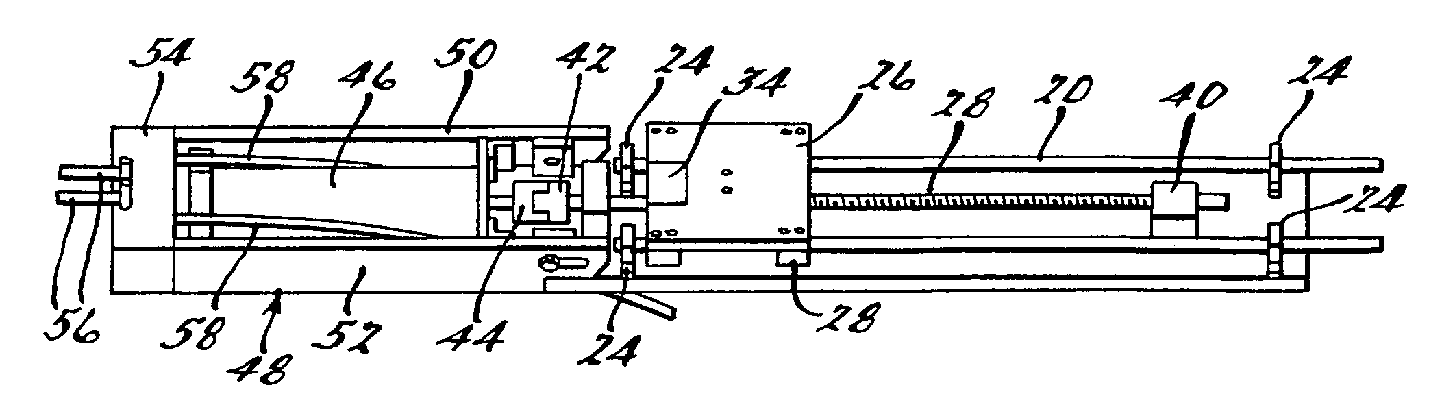
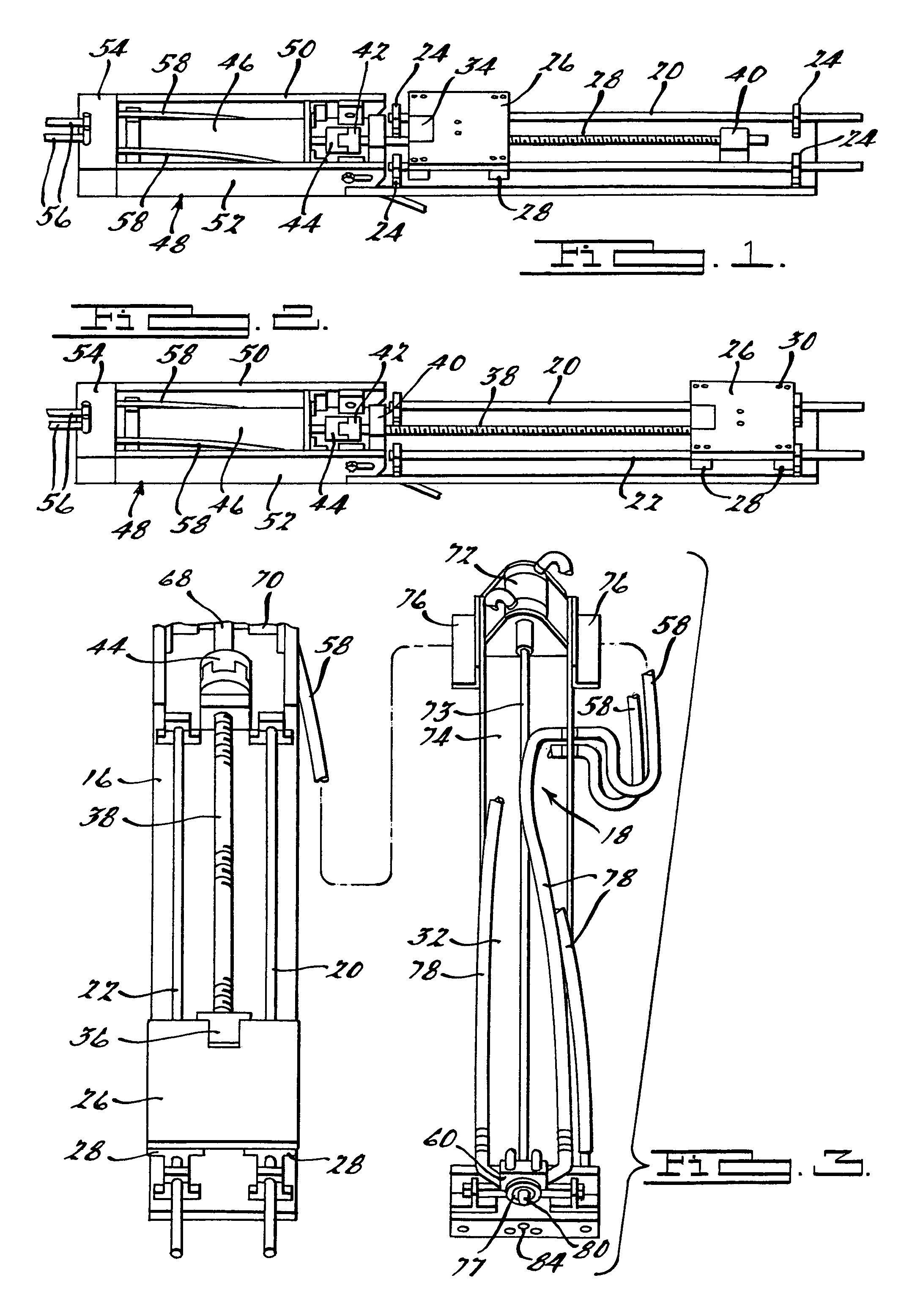
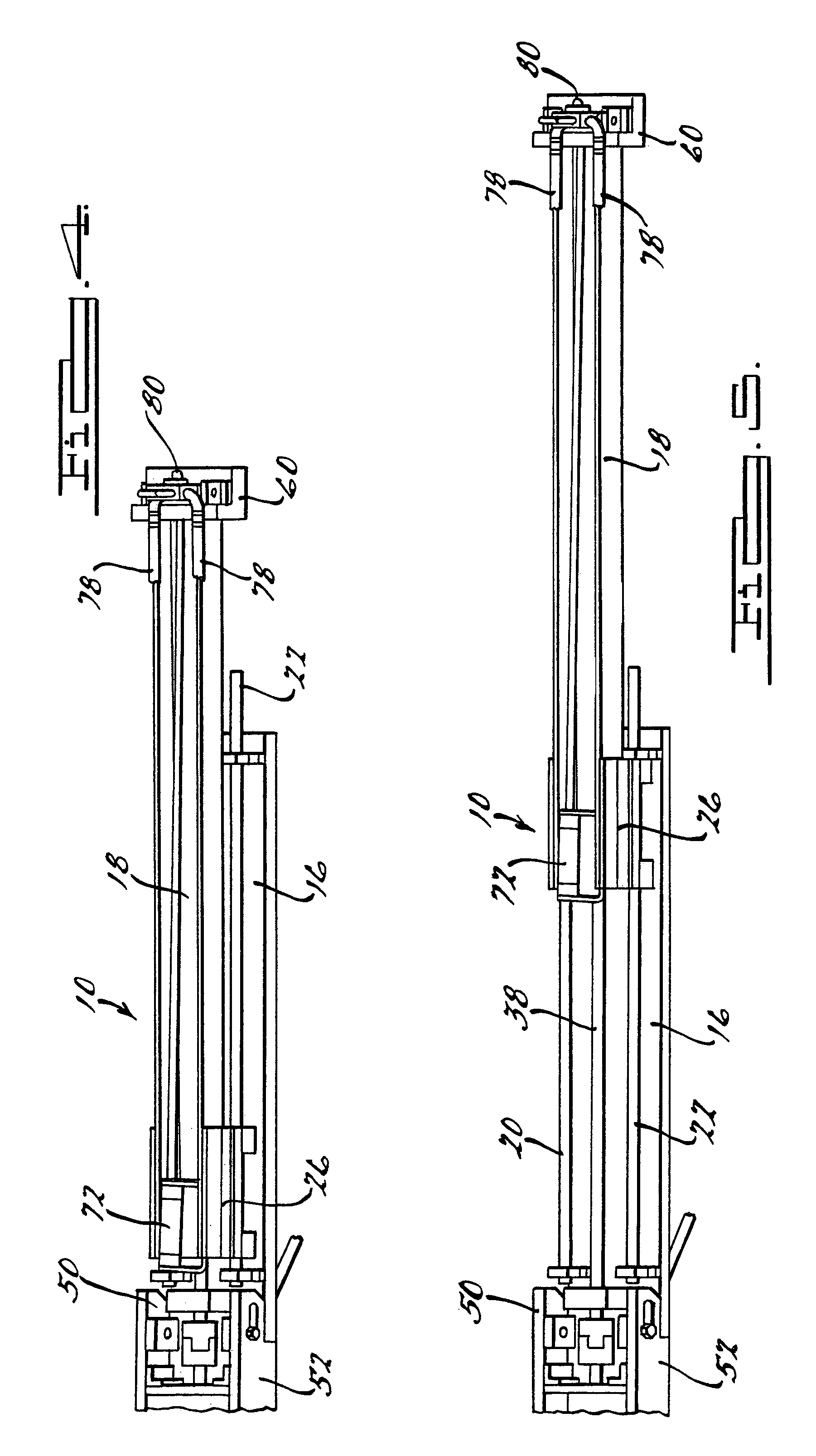
[0044]Referring to the drawings, a sprayed in place pipe liner apparatus 10 and method according to the present invention is shown. The sprayed in place pipe liner apparatus 10 is for use in any known new pipeline or any known pipeline in need of rehabilitation. The sprayed in place pipeline apparatus 10 is capable of being placed through existing man hole covers or placed through another cut in the pipe, such as but not limited to those man made through excavating or the like. The spray in place pipe liner apparatus 10 in one embodiment will be a robot that is capable of having a camera mounted thereon and is capable of being moved through a pipe 12 and will disperse a fast cured coating onto the interior of the pipe 12 being lined. It should be noted that the robotic apparatus 10 may not have a camera attached thereto. The robotic apparatus 10 will be moved through pipelines for rehabilitation on sliding rails 14 that have curved lead ends on one, neither or both ends thereof. Th...


PUM

PropertyMeasurementUnit
lengthaaaaaaaaaa
oblique angleaaaaaaaaaa
thickaaaaaaaaaa

Abstract

A method and apparatus for applying a liner to a pipe is disclosed. The apparatus includes a base assembly having a plurality of guide rails and a shuttle plate attached thereto. The apparatus also includes a motor module attached to an end of the base assembly. An extension arm is connected to a top surface of the shuttle plate. The extension arm has a spray head assembly attached at an opposite end thereof. The extension arm and spray head assembly will move relative to the base assembly of the apparatus. A fast cure coating will be applied via the spray head assembly to the interior surface of a pipe being rehabilitated. The spray head assembly will have an air blow off mechanism therein thus allowing for the tip of the spray head assembly to stay relatively clog free during the fast cure coating operation of the apparatus. The methodology also includes an oscillation system wherein the spray head assembly will move relative to the base assembly thus creating an over lapping pattern for the spray coating being applied to the interior surface of the pipeline. This oscillation system will allow for a more uniform coating to be applied.

Description

FIELD OF THE INVENTION[0001]The present invention generally relates to apparatuses and methods for coating the interior surface of a pipeline and more particularly relates to spraying a coating to form a liner within a pipeline environment.DESCRIPTION OF RELATED ART[0002]It is well known in the prior art to recondition the interior of pipes within existing or new sewer or another type of under ground pipe systems by any of the known prior art methods and apparatuses. Many of the under ground pipelines maybe corroded, have other problems that require fixing or total replacement or may be a new pipe section that requires a liner. Total replacement of these pipelines is very often both economically and practically not feasible because of downtime of the pipeline and the costs involved in excavating and laying new pipelines. Hence, this prior art method of locating the most seriously deteriorated sections of a pipeline and then excavating such section of pipe and patching or replacing t...

Claims


Application Information

Patent Timeline
Patent Type & Authority Patents(United States)
IPC IPC(8): B05B13/06B05B3/10B05B15/04B05D1/02F16L55/1645
CPCB05B13/0636B05B15/0443F16L55/1645B05B3/1014Y10S118/10B05D2254/04B05D1/02B05B12/36
Inventor DAVIS, THOMAS
Owner THE HANSON GROUP
Why Eureka
Try Eureka