
Apparatus and method for providing true geodetic coordinates

a geodetic coordinate and applicator technology, applied in the direction of speed measurement using gyroscopic effects, surveying and navigation, instruments, etc., can solve the problems of cumbersome portable systems, limited usefulness of known instruments for aiding in the use of maps, and inability to provide accurate geodetic coordinates

Inactive Publication Date: 2006-01-17
THE UNITED STATES OF AMERICA AS REPRESENTED BY THE SECRETARY OF THE NAVY
View PDF5 Cites 35 Cited by
  • Summary
  • Abstract
  • Description
  • Claims
  • Application Information

AI Technical Summary

Benefits of technology

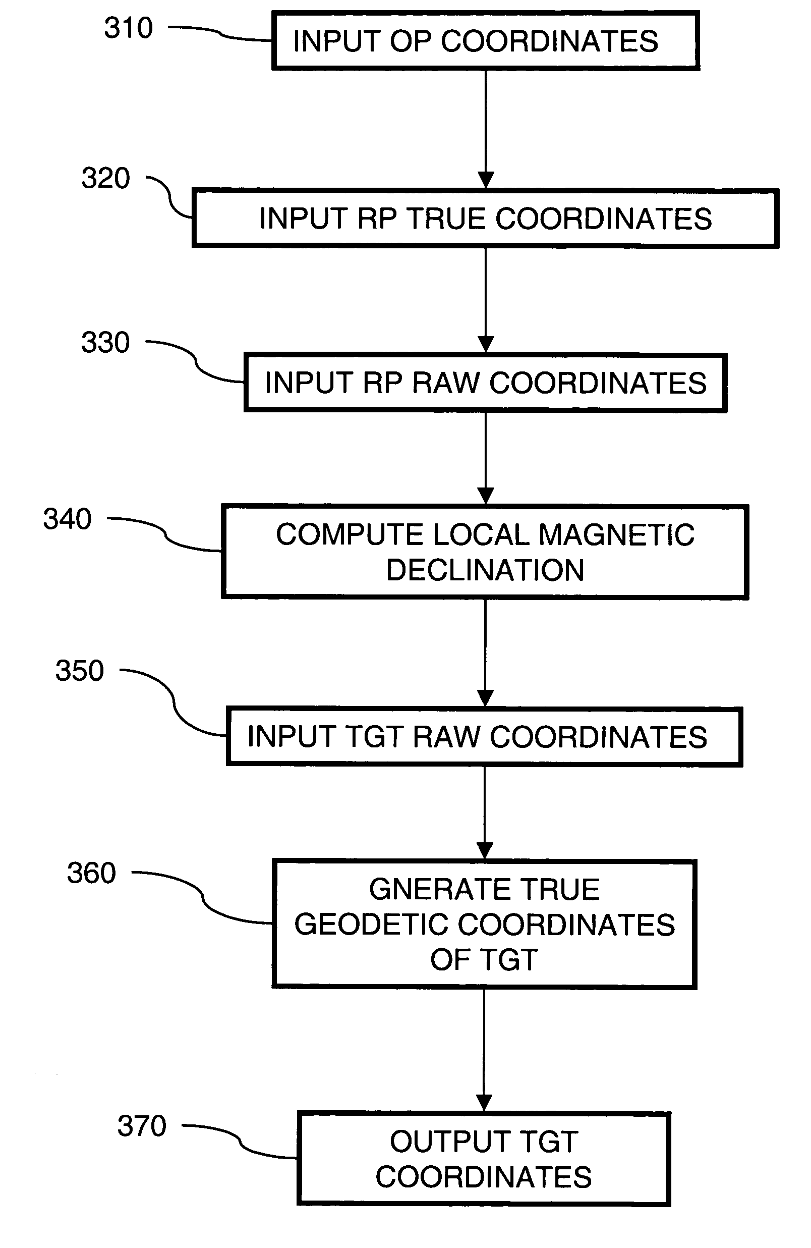
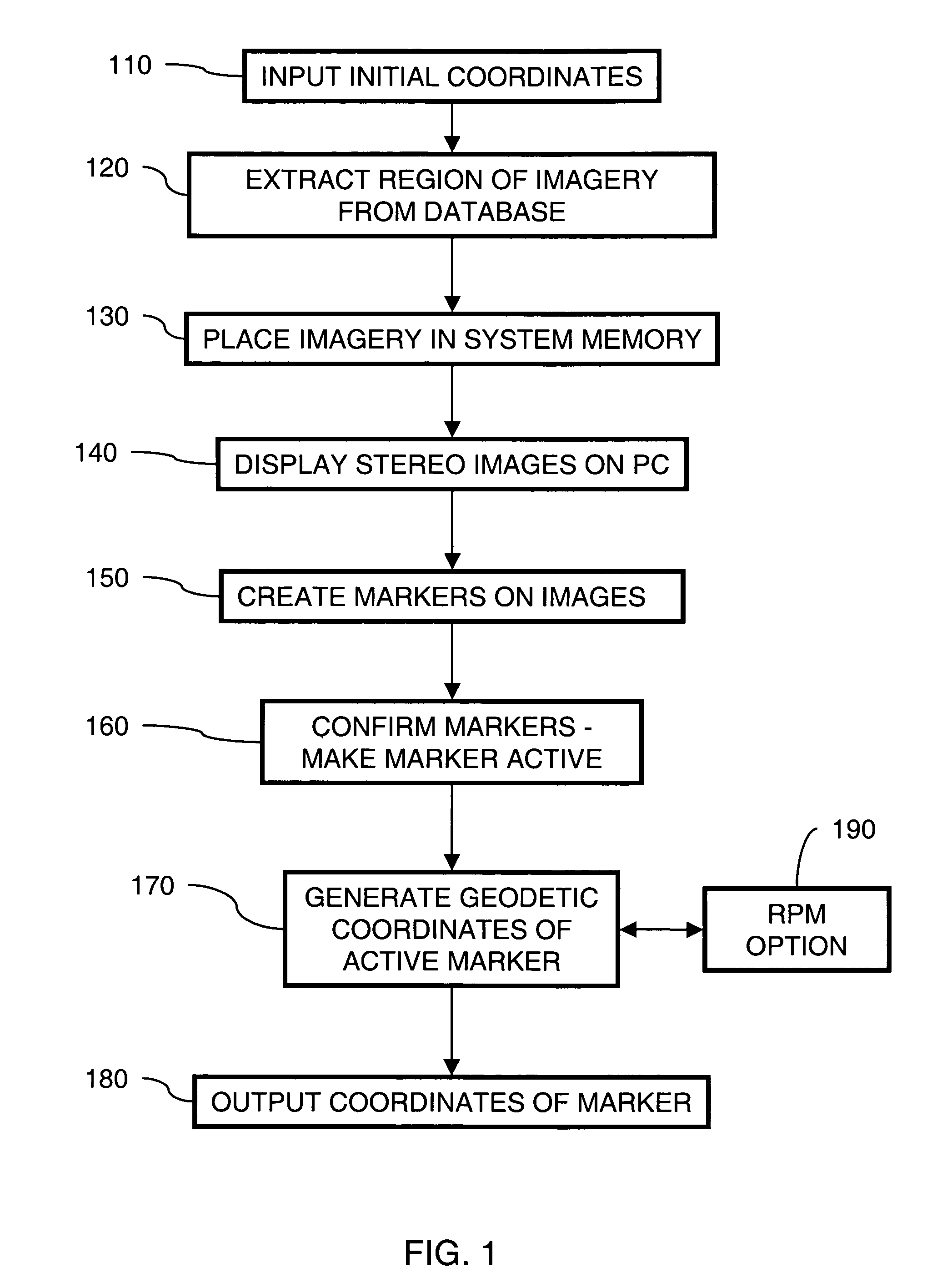
The invention provides an apparatus, method, and computer program for accurately positioning a target using an image database. This involves accepting input of true geodetic coordinates of an own position, raw coordinates of a reference point, and true coordinates of the reference point obtained from the image database. The system then calculates the exact local magnetic declination variance between the raw coordinates of the reference point and the true geodetic coordinates of the reference point. Using this information, the system calculates the true geodetic coordinates of the target position, and outputs the results. The technical effect of this invention is to provide accurate positioning of a target using an image database, which can be useful in various applications such as navigation and sports equipment design.

Problems solved by technology

Often this includes teams of observers equipped with various and cumbersome portable systems to either determine target position coordinates or to designate the target by laser illumination in the case of laser homing systems.
In addition, determining a true bearing to a target or a location is a concern due to the difference between magnetic readings of raw and true directions.
Known instruments for aiding in the use of maps, are very limited in their usefulness, particularly for military purposes.
One such limitation is that they are applicable to a single scale map because each instrument is calibrated for use with one of several military scaled maps, as for example 1:25,000, 1:50,000 or 1:125,000.
Another limitation of known instruments, particularly for military uses, is that the user has a need in the effective use of a map to make arithmatical computations and, therefore, military recruits must undergo extensive training in map reading.
A further limitation of known map reading devices is that the artillery uses instruments in which angular directions are measured in mils rather than degrees for more accurate aiming of the weapons.
Obviously, where in the use of heretofore known map reading instruments computations are required, the need for paper and / or a writing implement poses a problem, particularly under actual field conditions where paper and a writing tool is not, always available to the map user.
Determining target coordinates in the field is cumbersome and prone to error using the methods described.

Method used


Image

  • Apparatus and method for providing true geodetic coordinates
  • Apparatus and method for providing true geodetic coordinates
  • Apparatus and method for providing true geodetic coordinates

Examples


Embodiment Construction

[0015]Embodiments of the present invention include an apparatus and method for providing true geodetic coordinates for locations, which may be used in targeting of weapons. It should be understood that the examples and embodiments described herein are for illustrative purposes only and that various modifications or changes in light thereof will be suggested to persons skilled in the art and are to be included within the spirit and purview of this application and the scope of the appended claims.

[0016]An embodiment of the invention includes a rugged handheld personal computer (PC) such as, for example Panasonic Toughbooks™ CF-18, CF-27, CF-34, CF-50, CF-72; IBM A-21P, A-31P, and Dell Inspiron™ laptops, housed in portable, tough, resilient cases. The PC runs the Precision Strike Suite (PSS) and the Reference Point Method (RPM) programs that may be windows based input and display programs that provide a user friendly interface to receive input and display results. The PC may receive an...


PUM


Abstract

An embodiment of the present invention utilizes the Reference Point Method (RPM). RPM generates a local magnetic declination variance that is exact for the location of the OP, utilizing an optical stereo imagery database. RPM functions to determine true geodetic coordinates of a target position not available to be displayed in an image database, such as, for example, movable equipment.

Description

CROSS-REFERENCE TO RELATED APPLICATIONS[0001]This application claims priority under 35 U.S.C. §119(e) of U.S. provisional application having Ser. No. 60 / 540,901 filed on Jan. 28, 2004, which is hereby incorporated by reference. This application is co-pending and was concurrently filed with U.S. patent application having Navy Case No. 84647.STATEMENT REGARDING FEDERALLY SPONSORED RESEARCH OR DEVELOPMENT[0002]The invention described herein may be manufactured and used by or for the government of the United States of America for governmental purposes without the payment of any royalties thereon or therefor.BACKGROUND OF THE INVENTION[0003]For weapons systems to be effective, the location of a target must be known in a coordinate system, such as longitude, latitude and elevation. These coordinates must be extremely accurate in order to properly guide a weapon and to avoid collateral damage.[0004]In the past attempts have been made to improve the determination of coordinates. Often this ...

Claims


Application Information

Patent Timeline
Patent Type & Authority Patents(United States)
IPC IPC(8): G01C17/00
CPCG01C21/20G01C17/00
Inventor WIRTZ, MICHAEL MATHEWHAVLIN, MICHAEL ROBERTTILLEY, DIANE SUEMODLINSKI, FRANK JOSEPHTHOMAS, MICHAEL DAVIDMILLER, LOUIS CHRISTOPHERDITZLER, WILLIAM RODNEYMCKNIGHT, JAMES EDWARD
Owner THE UNITED STATES OF AMERICA AS REPRESENTED BY THE SECRETARY OF THE NAVY
Learn More