Al technical title is built by PatSnap Al team. It summarizes the technical point description of the patent document.
a drive device and adjustable technology, applied in the direction of manufacturing tools, stapling tools, nailing tools, etc., can solve the problems of difficult to achieve and one speed of adjusting
Inactive Publication Date: 2006-01-24
ILLINOIS TOOL WORKS INC
View PDF25 Cites 31 Cited by
Summary
Abstract
Description
Claims
Application Information
AI Technical Summary
This helps you quickly interpret patents by identifying the three key elements:
Problems solved by technology
Method used
Benefits of technology
[0012]The above-listed objects are met or excluded by the present adjustable depth of drive device for use on a fastener driving tool, such as a combustion type framing tool or the like. An important feature of the present device is a spring loaded thumb wheel or barrel which is constructed and arranged to adjust the position of the workpiece contact element relative to the nosepiece so that either gross or fine adjustments may be made in virtually the same user motion, without the use of complicated latch mechanisms.
[0013]More specifically, the present invention provides an adjustable depth of drive device for use on a fastener driving tool having a housing structure which defines an axis, and encloses a combustion chamber, and a nosepiece which extends generally axially from the housing with a workpiece contact element. The device includes a thumb post which is mounted to, and extends from the workpiece contact element. A thumb wheel is adjustably engaged on the thumb post, and a spring member is engagable with the thumb wheel in at least two positions. In a first position, the spring member is frictionally engaged with the thumb wheel to prevent unwanted movement of the thumb wheel relative to the thumb post. In a second position, the spring member is disengaged from the thumb wheel to permit free rotation of the thumb wheel on the thumb post.
[0014]The spring member exerts a biasing force against the thumb wheel, and in the first position, the thumb wheel is manually movable when the biasing force is overcome, allowing for fine adjustments of the position of the work piece contact element relative to the nosepiece. Also, in the preferred embodiment, the spring member has a thumb lever for moving the spring member into the second position, allowing for gross adjustments of the position of the workpiece contacting element relative to the nosepiece.
Problems solved by technology
One disadvantage of previous depth adjusting mechanisms is that they will only allow one speed of adjusting, usually gross adjustment.
This can be difficult to accomplish when the adjusting mechanism only allows for gross adjustments, and therefore the user may have to adjust the depth of drive several times through trial and error in order to obtain the correct measurement for the depth of drive.
Method used
Image
Click on the blue label to locate the original text in one second.
Reading with bidirectional positioning of images and text.
Examples
Embodiment Construction
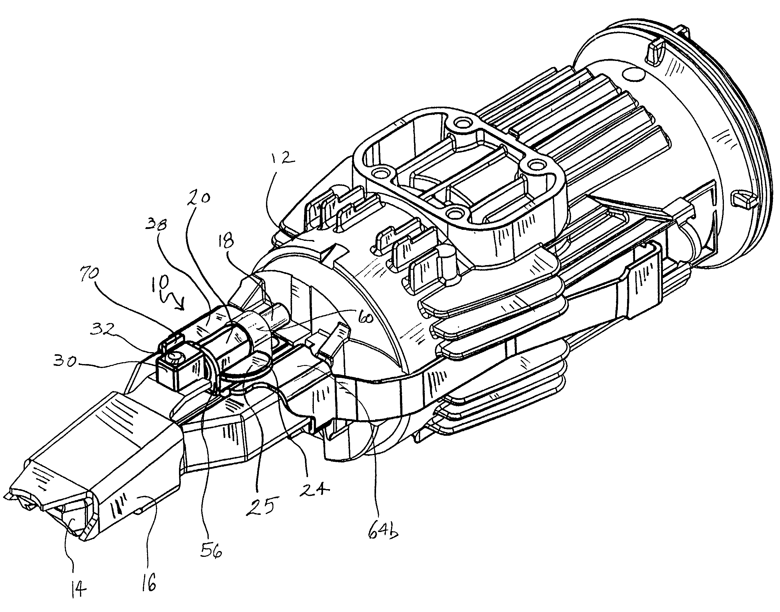
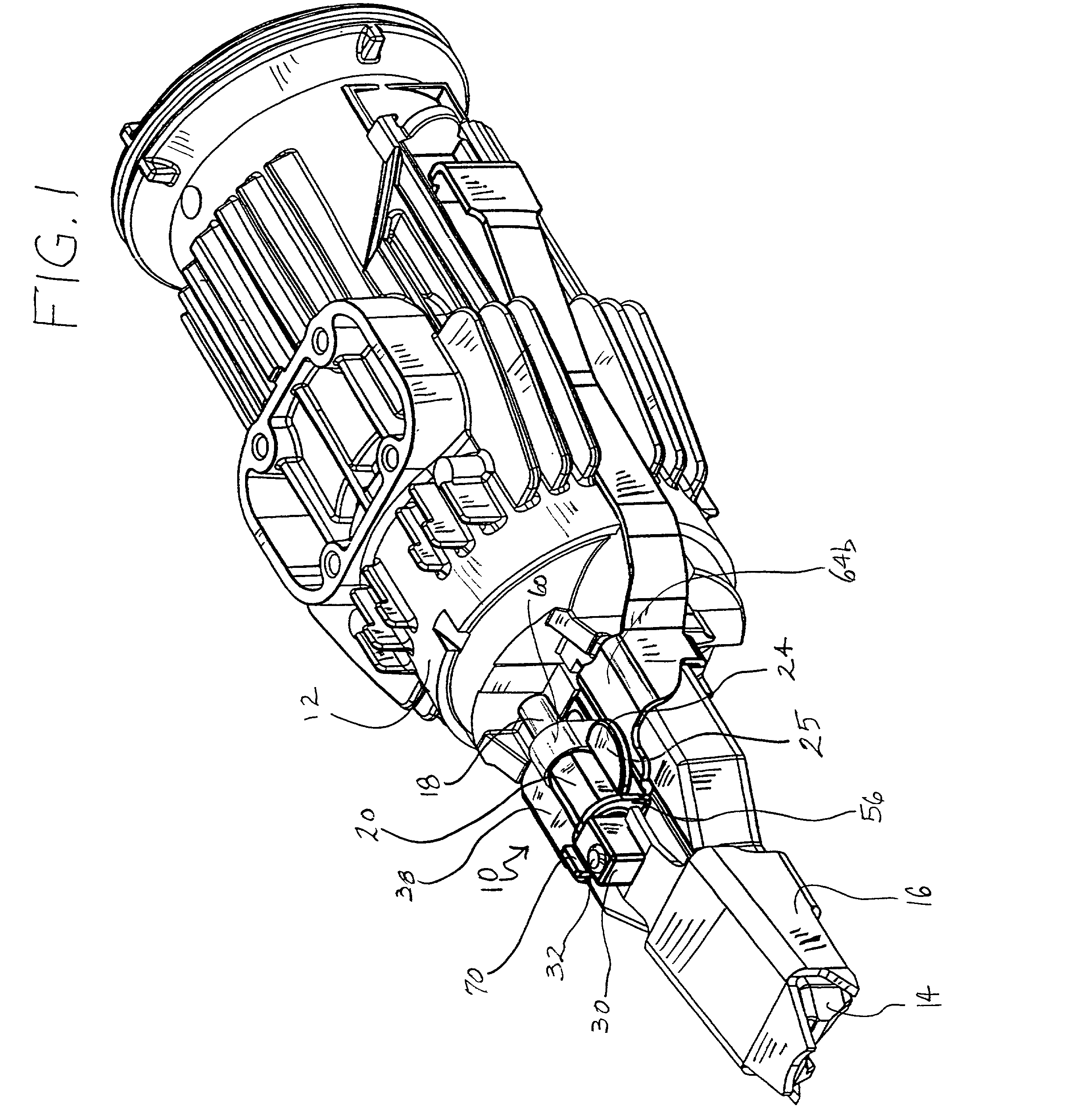
[0018]As seen in FIG. 1, an improved adjustable depth of drive device is generally designated 10, and is intended for use on a fastener driving tool of the type described above. The tool includes a housing or sleeve structure 12 which defines an axis and encloses a combustion chamber (not shown), and a nosepiece 14 which extends axially from the housing structure, along with a work piece contact element 16.
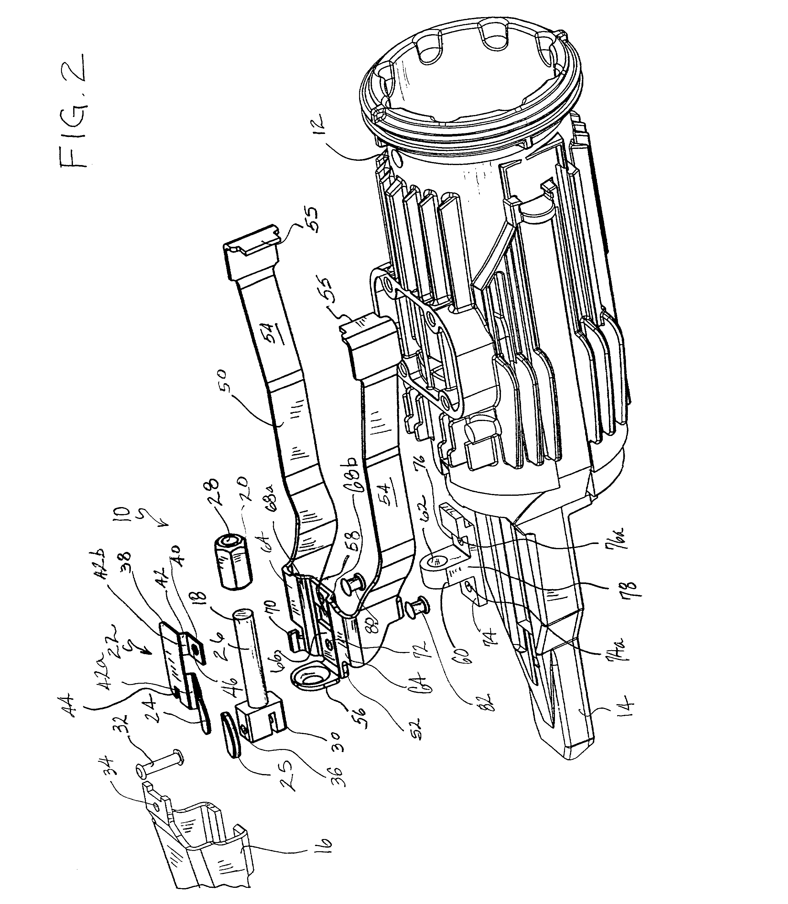
[0019]Referring now to FIG. 2, the adjustable depth of drive device 10 includes a thumb post 18 which is mounted to, and extends from the work piece contact element 16. There is also a thumb wheel 20 which is removably attached to, and adjustably engaged on the thumb post 18, and a spring member, generally designated 22, that is engagable with the thumb wheel in at least two positions. In a first position, seen in FIG. 1, the spring member 22 is frictionally engaged with the thumb wheel 20 to prevent unwanted movement of the thumb wheel relative to the thumb post 18. In a second p...
PUM
Property
Measurement
Unit
depth
aaaaa
aaaaa
depth of drive
aaaaa
aaaaa
volume
aaaaa
aaaaa
Abstract
An adjustable depth of drive device for use on a fastener driving tool. The adjustable depth of drive device includes a thumb post which is mounted to, and extends from a work piece contact element of the tool. Also included is a thumb wheel which is removably attached to the thumb post. A spring member is another part of the adjustable depth of drive device, and it is engagable with the thumb wheel in at least two positions. In a first position, the spring member is frictionally engaged with the thumb wheel to prevent unwanted movement of the thumb wheel relative to the thumb post, and this first position allows for fine adjustments of the position of the work piece contact element. In a second position, the spring member is disengaged from the thumb wheel to permit free rotation of the thumb wheel on the thumb post, which allows for gross adjustments of the position of the work piece contact element.
Description
[0001]The present invention relates generally to fastener driving tools such as combustion powered tools, pneumatic tools, cordless framing tools and the like. More particularly, the present invention relates to improvements in a device which adjusts the depth of drive of the tool.BACKGROUND OF THE INVENTION[0002]As exemplified in Nikolich, U.S. Pat. Re. No. 32,452, and U.S. Pat. Nos. 4,552,162; 4,483,473; 4,483,474; 4,404,722; 5,197,646; 5,263,439; 5,558,264 and 5,678,899 all of which are incorporated by reference, fastening tools, and particularly, portable combustion powered tools for use in driving fasteners into workpieces are described. Such fastener-driving tools are available commercially from ITW-Paslode (a division of Illinois Tool Works, Inc.) of Vernon Hills, Ill., under the IMPULSE® brand.[0003]Such tools incorporate a generally gun-shaped tool housing enclosing a small internal combustion engine. The engine is powered by a canister of pressurized fuel gas, also called ...
Claims
Application Information
Patent Timeline
Application Date:The date an application was filed.
Publication Date:The date a patent or application was officially published.
First Publication Date:The earliest publication date of a patent with the same application number.
Issue Date:Publication date of the patent grant document.
PCT Entry Date:The Entry date of PCT National Phase.
Estimated Expiry Date:The statutory expiry date of a patent right according to the Patent Law, and it is the longest term of protection that the patent right can achieve without the termination of the patent right due to other reasons(Term extension factor has been taken into account ).
Invalid Date:Actual expiry date is based on effective date or publication date of legal transaction data of invalid patent.
Patent Type & Authority Patents(United States)
IPC IPC(8): B25C1/04B25C1/00B25C1/08
CPCB25C1/08B25C1/008
Inventor TAYLOR, WALTER J.SHKOLNIKOV, YURYECKARDT, JEFFREY G.