Apparatus for handling and racking pipes

a technology for manipulating and racking pipes, which is applied in the direction of manipulators, transportation and packaging, cutting heads, etc. it can solve the problems of affecting the efficiency of racking, the bottom end of the stand is prone to swinging, and the drilling string must be tripped out of the hole frequently, so as to increase the racking efficiency and the rate of racking

Inactive Publication Date: 2009-10-15
WEATHERFORD CANADA
View PDF31 Cites 29 Cited by
  • Summary
  • Abstract
  • Description
  • Claims
  • Application Information

AI Technical Summary

Benefits of technology

[0017]In accordance with the present invention, there is provided an apparatus for handling pipes in a drilling derrick wherein the apparatus stabilizes and supports the pipe stand such that unwanted movement of the pipe stand, which affects the rate of racking, may be reduced, thereby increasing racking efficiency
[0018]In summary, the pipe stand racking system according to the present invention includes a racking board, an overhead frame for supporting the articulated arm mounted at the end of the diving board to the racking board, a rotation drive on the end of the driving board cantilevered in the open corridor between the fingers of the racking board, a parallelogram arm mounted to the rotation drive and a pipe stand gripper mounted to the arm. The overhead frame helps support the weight of the rotation drive, arm, gripper and any pipe stand being lifted. The arm is rotated and extended so as to position the gripper along linear paths corresponding to the open corridor and finger spacing's between the finger by coordination of rotation and extension of the arm as controlled by a controller. Pipe stands are thereby lifted and carried between well center and next available positions in the racking board.
[0022]When the first frame is mounted to the derrick mast, in. its extended position the parallelogram arm has a reach sufficient to position the gripper at well center when the rotation drive is in a first rotational position. When the rotation drive is in a second rotational position the reach of the parallelogram arm is sufficient to place a pipe stand held in the gripper into a rear-most finger space between the back wall of the first frame and an adjacent finger of corresponding the array of pipe stand supporting fingers. When the parallelogram arm is in its retracted position, the gripper is rotatable by rotation of the parallelogram arm by the rotation drive along an arc having a retracted radius corresponding to rotation of the gripper and the parallelogram arm. The retracted radius allows rotation of the gripper about the axis of rotation within the corridor without interference with the ends of the fingers in the opposed facing arrays of pipe supporting fingers closest to the corridor. The gripper and the parallelogram arm are extendible between the retracted and extended positions when the rotation drive is in the first rotational position. The gripper and the parallelogram arm are rotatable by the rotation drive between the first and second rotational positions when the parallelogram arm is in the retracted position.
[0023]The spacing between the cantilevered member and the terminal ends of the fingers define at least one corridor space for passing there-along an end of a pipe stand held in the gripper. Each pipe stand may thus be moved back and forth from well center to the racking board. The weight of the pipe stand is transferred to front legs of the mast via the overhead second frame mounted above the racking board and through the racking board to the derrick mast so as to support the weight of the pipe stand from above whereby each full pipe stand may be lifted for positioning of the full stand.
[0026]The accelerations and decelerations of the gripper and the pipe stand being carried along the constrained path are optimized to minimize pipe stand instability, to smooth motion of the pipe stand along the constrained path, and to minimize probability of impact of a pipe stand held by the gripper with the racking board during translation along the constrained path. In order to accomplish this rotational and extension motions of the arm are coordinated together to create straight line movement of the gripper and a pipe stand held therein along the first and second linear paths.

Problems solved by technology

Because the drill bit has to be changed after a few days or even a few hours, depending on the hardness of the matter being drilled through, the drill string must be tripped out of the hole frequently.
This can be reasonably efficient when done by a skilled derrickman but, especially on a 10 or 12 hour round trip, it will be exhausting.
These systems are not practical for land drilling rigs.
When pipe stands are racked manually, there is considerable swinging of the bottom end of the stand when it is lifted with the drawworks.
This can put personnel at risk of injury.
While the prior art provides devices for handling pipe stands in a more efficient manner, they do not provide a solution to address the instability associated with manipulating and transporting pipe stands that may exceed ninety feet in length and several thousand pounds in weight.
Therefore, an unaddressed need exists in the industry to provide an apparatus for handling pipes in a stable and efficient manner to deal with deficiencies and inadequacies in the prior art.

Method used


Image

  • Apparatus for handling and racking pipes
  • Apparatus for handling and racking pipes
  • Apparatus for handling and racking pipes

Examples


Embodiment Construction

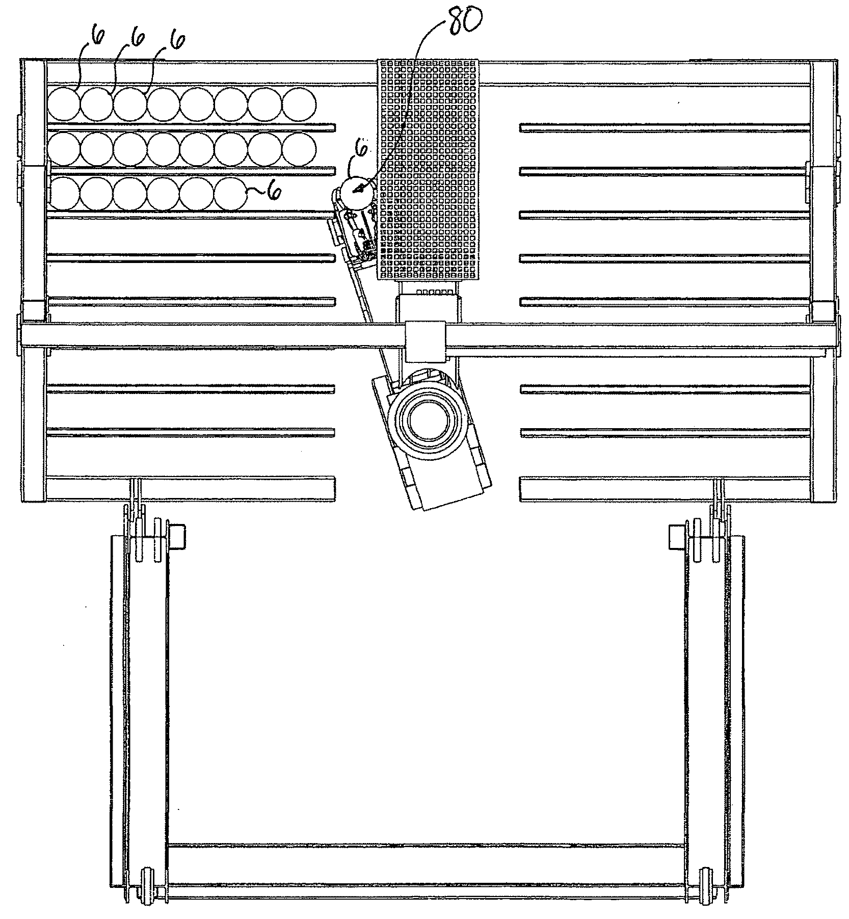
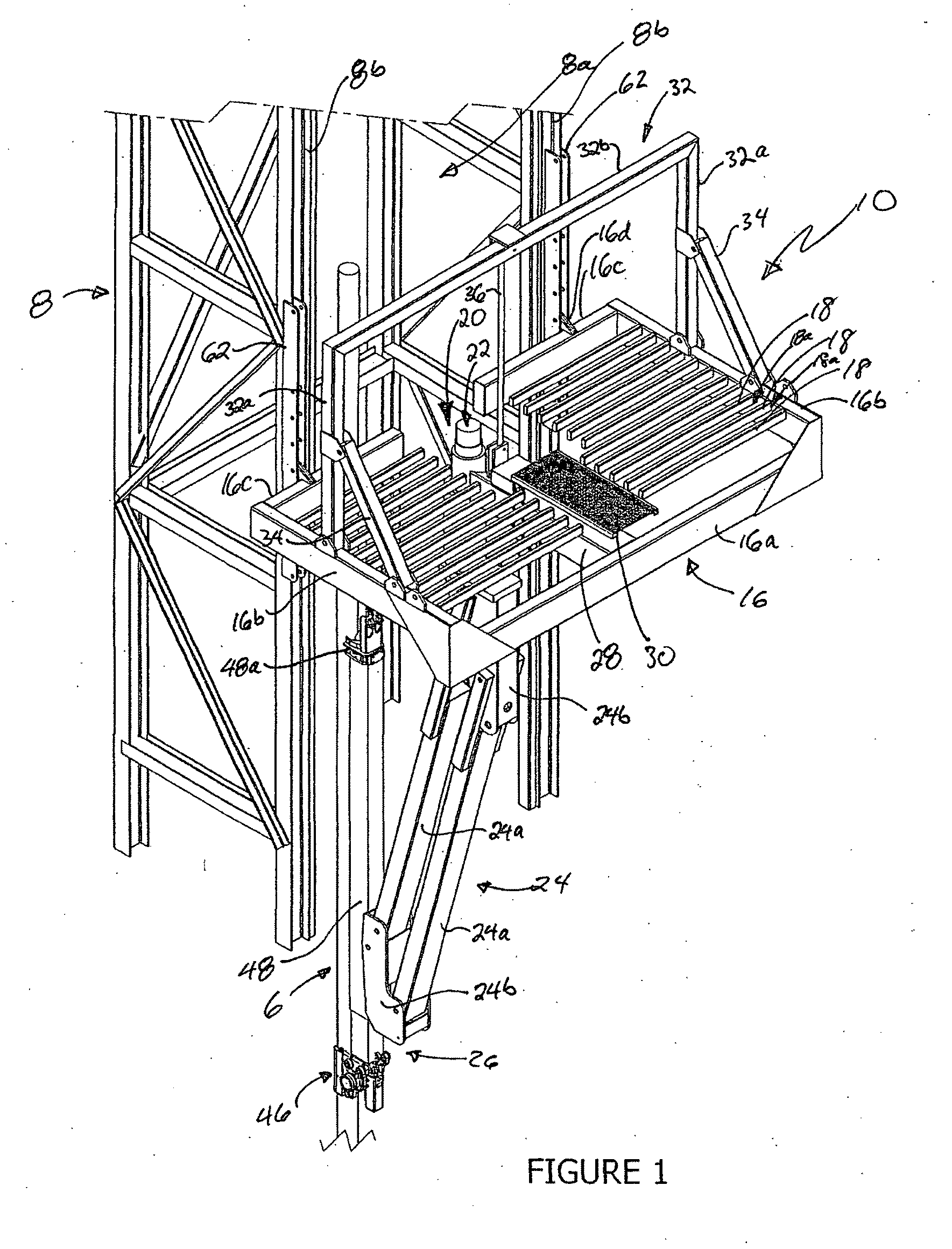
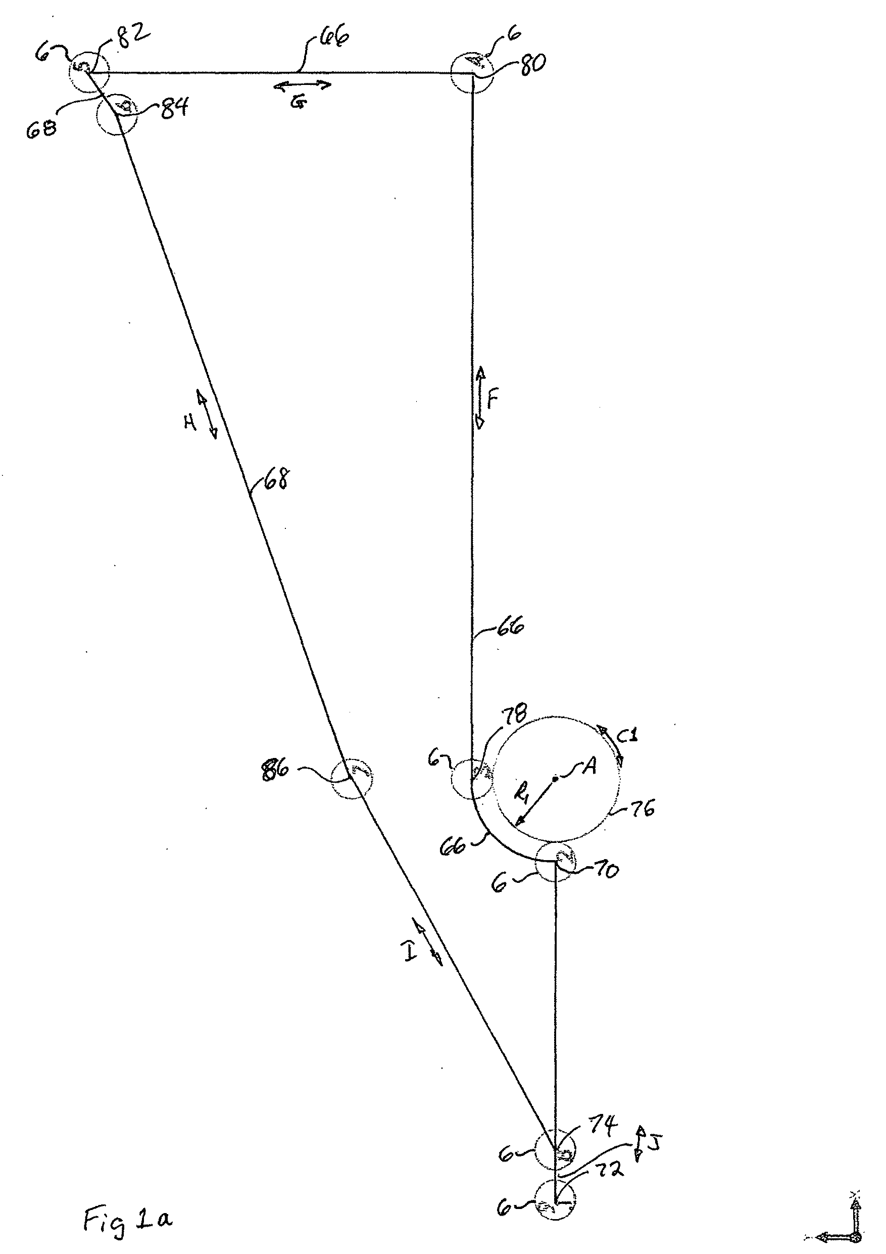
[0065]With reference to the Figures wherein similar characters of reference denote corresponding parts in each view, the apparatus for handling pipe stands 6 includes a derrick 8, a pipe racking assembly 10 mounted to derrick 8. A rotatable and articulated assembly 20 is mounted to pipe racking assembly 10 in a central open corridor 12. In an embodiment of the present invention, the apparatus for handling pipes is configured to handle and rack a plurality of pipe stands 6 which are triple stands or larger. In use the pipe stands are detachably coupled together to form a drill string 14.

[0066]In an embodiment of the invention, pipe racking assembly 10 is generally rectangular in shape and horizontally disposed. Pipe racking assembly 10 is mounted to a mid-portion of derrick 8 such that pipe racking assembly 10 extends outwards and away from derrick 8. Pipe racking assembly 10 includes a first frame 16 and a plurality of transversely disposed support members such as fingers 18 mounted...


PUM


Abstract

An apparatus for handling pipes in a derrick and racking the pipes on a pipe racking assembly mounted on the derrick is provided to improve the stability of transferring pipes during a round trip operation.

Description

CROSS REFERENCE TO RELATED APPLICATIONS[0001]This application is a continuation-in-part of patent application Ser No. 11 / 785,446 filed Apr. 18, 2007, which is a continuation-in-part of patent application Ser. No. 10 / 997,930 filed Nov. 29, 2004, now U.S. Pat. No. 7,331,746 which issued Feb. 19, 2008.FIELD OF THE INVENTION[0002]This invention relates to the field of equipment used in the drilling industry, and more particularly, it relates to an apparatus for manipulating and racking pipes in a drilling derrick.BACKGROUND OF THE INVENTION[0003]In drilling operations, the derrick is the structure designed to support and manipulate the drill string in and out of the well bore. The drill string is a series of drill pipe segments or joints detachably connected together. Typically, the drill pipe joints are coupled together to form a pipe stand consisting of two or three joints of pipe. The stands are then coupled together to form the drill string.[0004]Drill collars and a drill bit are at...

Claims


Application Information

Patent Timeline
Patent Type & Authority Applications(United States)
IPC IPC(8): E21B19/14E21B19/00B25J15/00
CPCE21B19/14Y10S414/13
Inventor STROSHEIN, WILLIAM JOHNRICHARD, DAVID LOUISWRIGHT, MONTE NEILJANTZEN, LEON KEITHASSAF, IMAD
Owner WEATHERFORD CANADA
Why Eureka
Try Eureka